Warner Electric ERDD Sizes 120 to 600 User Manual
Page 3
Warner Electric Europe • +33 (0)2 41 21 24 24
P-2064-WE • 2/13 3
3
Installation
3.1
Transport / storage
These units are delivered in packaging that
guarantees a 6 months storage period whether
transported by land, by air, or by sea to any
destination excepting tropical countries. (For
tropical destinations please consult Warner
Electric technical services).
3.2
Handling
Avoid any impacts on the equipment so as not
to alter their performance.
Never carry the equipment by the electrical
supply cable.
3.3
Installing
NB : ERD SZ060 to 300 brakes are supplied in
kit form. The Mounted inductor is supplied
airgap adjusted.
The ERDD HT brakes are delivered completely
mounted, the airgap is adjusted in our
workshop. See chapter 7 (appendix)
If a friction flange (341) is supplied, fix it first.
Put the key into the shaft then slide the hub
(515) onto the shaft and stop it axially by
suitable means.
Slide the friction disc (312) or (315) onto the
hub.
Fit the mounted inductor (107) or (108), remove
the wedge pieces (551) and fix it using the
fixing bolts (913) or (914).These screws have
to be tightened (see torque table 1). Secure the
bolts using a LOCTITE 270 type thermoplastic
liquid.
If a hand locking kit is supplied, it is preferable
to adapt it on the mounted inductor before the
inductor is fitted. (See chapter 6)
If a dust cover (555) is supplied, carefully slide it
onto the equipment before fitting it.
Switch
the equipment on and confirm that the
friction disc rotates freely.
Make several motor manoeuvres stationary and
check the value of the airgap.
If the airgap is insufficient, refer to chapter 4
(maintenance)
Do not grease the guiding splines (friction
disc / hub). It will change the brake’s
performances.
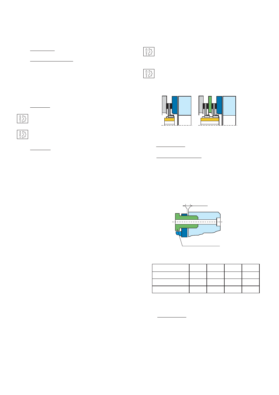
WATCH OUT ! Respect obligatory the direction
of the hub when mounting (see fig. 1 below)
4
Maintenance
4.1
Adjusting the airgap
To
adjust the airgap (Fig. 2), undo the adjustment
bolts in order to get the necessary value (see table
1). Check the value of the airgap at several points.
Make several motor manoeuvres stationary, then
again check the value of the airgap.
4.2
Maintenance
Wear in the friction material causes an increase
in the air gap. Before reaching the maximum
airgap (see table 1), it is necessary adjust it (see
above).
Fig. 1
ERD
ERDD HT
Table 2
Adjusting screw
Airgap
Fig. 2
ERD Size
060
100
170
300
E min (mm)
6
6
7,7
8
ERDD HT Size
120
200
340
600
E min (mm)
11,2
10
12,7
12,3