Warner Electric ERDD Sizes 120 to 600 User Manual
Page 2
2 Warner Electric Europe • +33 (0)2 41 21 24 24
P-2064-WE • 2/13
We,
WARNER ELECTRIC EUROPE, 7, rue Champfleur, B.P. 20095, F-49182 St Barthélemy d’Anjou Cedex
declare that the brakes herein made in our factory from St Barthélemy d’Anjou,
ERD and ERDD
are intended to be incorporated in an installation or to be assembled with other equipment with a view to constituting a machine to which
directive 89/336 as amended apply.
The basic requirements of Low Voltage directive 73/23 as amended are compiled with through full conformity with the following standards:
NFC 79300 and VDE 05808/8.65
Drawn up in St Barthélemy d’Anjou, July 2002
E. PRAT, General Managing Director
CONTENTS
1
Technical specifications
2
2
Precautions and restrictions on use
2
2.1
Restrictions on use
2
2.2
Precautions and safety measures
2-3
3
Installation
3
3.1
Transport - storage
3
3.2
Handling
3
3.3
Installing
3
4
Maintenance
3
4.1
Adjusting the airgap
3
4.2
Maintenance
3
4.3
Spare parts
4
5
Electrical connection
4
5.1
Important recommendations
4
5.2
Power supply
4
6 Options
4
6.1
Torque adjustment
4
6.2
Detection kit
5
6.3
Hand release kit
5
7
Appendices
6
7. 1
ERD VAR00 and VAR02
7
7.2
ERDD and options
7
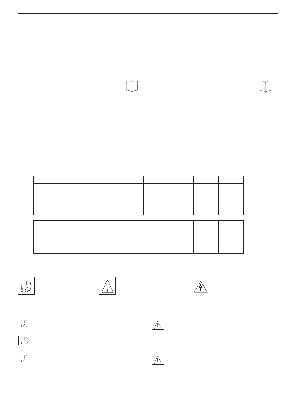
1
Technical specifications VAR00, VAR02
Table 1
ERD Size
060
100
170
300
Nominal torque (STANDARD version)
Nm
Nominal airgap +0,1/-0,05
mm
Pull-in airgap max.
mm
Nominal torque (HIGH TORQUE version) Nm
Tightening torque of screws
mm
60
0,3
0,8
80
24
100
0,3
0,9
130
24
170
0,3
0,9
220
24
300
0,3
1
400
48
ERDD HT Size
120
200
340
600
Nominal torque (HIGH TORQUE version) Nm
Nominal airgap +0,1/-0,05
mm
Pull-in airgap max.
mm
Tightening torque of screws
mm
160
0,3
0,8
24
260
0,4
0,9
24
440
0,4
0,9
24
800
0,4
1
48
2
Precautions and restrictions on use
2.1
Restrictions on use
The equipment is designed for dry
running.
Exceeding the maximum rotation speeds stated
in the catalogue invalidates the warranty.
The equipment can be fitted either horizontally or
vertically. The ERDD and HT version can only be
fitted horizontally.
This equipment is designed for an ambient
temperature of 40° maximum (155°C cladding
class).
2.2
Precautions and safety measures
During maintenance, ensure that the Mechanism
to be braked by the equipment is at rest and
that there is no risk of accidental start-up.
All intervention have to be made by qualified
personnel, owning this manual.
Any modification made to the brake without
the express authorisation of a representative of
Warner Electric, in the same way than any use
out of the contrac tual specifications accepted by
“Warner Electric”, will result in the warranty being
invalidated and Warner Electric will no longer be
liable in any way with regard to conformity.
Symbol designating
an action that might
damage the brake
Symbol designating an
action that might be
dan gerous to human safety
Symbol designating an
elec trical action that might be
dangerous to human safety