Warner Electric Electrically Released Brake ER-375, ER-475, ER-650 User Manual
Page 7
7
Warner Electric • 800-825-9050
P-253 • 819-0315
Fails to Release: If the Electrically Released
Brake does not release completely, make the
following checks:
1. Check that the electrical connections (polarity)
between the brake coil and the power supply
are correct for the power supply being used.
2. Connect a DC voltmeter across the brake
terminals. (Do not disconnect the leads to the
terminals.) The voltmeter should indicate a
voltage in the range of 75 to 110 volts.
3. The above checks are normally sufficient.
Further checks may be made by checking
the brake coil resistance.
a. Turn off the power to the brake.
b. Disconnect one lead from the coil to make
sure the circuit is open.
c. Connect an ohmmeter across the brake
terminals. The resistance should be as
shown:
Brake
Coil Resistance
Size
at 20°C (±10%)
ER-375
447 OHMS
ER-475
310 OHMS
ER-650
235 OHMS
A very high or infinite resistance reading would
indicate an open coil. A very low resistance
would indicate a shorted coil. In either case, the
unit should be replaced.
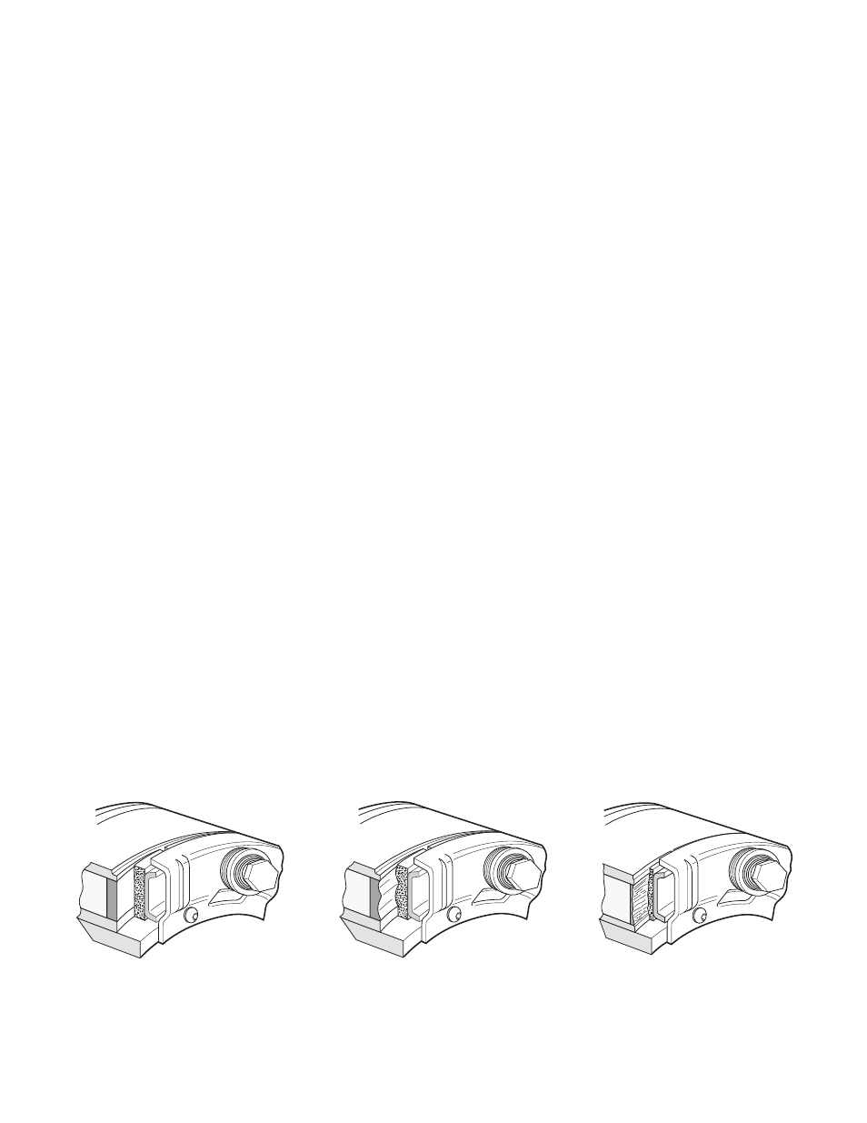
Wear Pattern
New
Burnished
Worn
Wear Pattern: (See Figure 5) Wear grooves appear
on the friction surfaces. This is a normal wear
condition, and does not impair functioning of the
unit. Never machine the friction surfaces to remove
grooves or score marks resulting from normal wear.
There are two main wear parts, magnet and
armature. When either is worn out, the complete
brake must be replaced.
Heat: Excessive heat and high operating
temperatures are causes of rapid wear. Air should
be allowed to circulate around the unit as efficiently
as possible, especially if the application requires
fast, repetitive cycle operation.
If the above checks indicate that the proper voltage
and current is being supplied to the coil, mechanical
parts should be checked to assure that they are in
good operating condition and are properly installed.
Figure 5