Warner Electric Electrically Released Brake ER-375, ER-475, ER-650 User Manual
Page 5
5
Warner Electric • 800-825-9050
P-253 • 819-0315
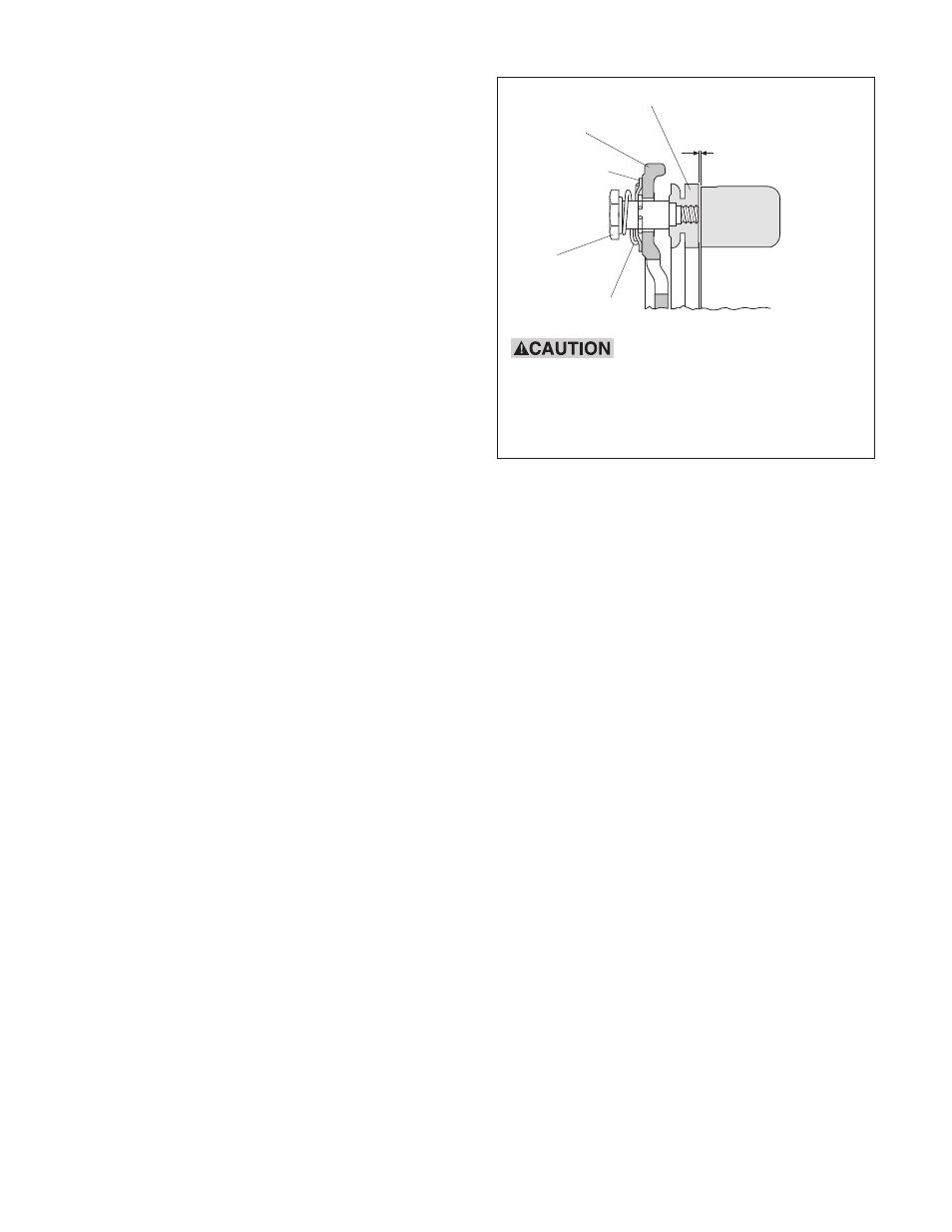
Armature
Carrier
Detent Spring
Retainer
Drive Pin
Detent Spring
Armature Spring
Back 1/32-inch
Magnet
Figure 4
A. With the brake power on, pull gently on the
O.D. of the armature to separate it from the
magnet by a 1/32-inch or greater airgap.
Do not pry. This could damage the
components.
B. Slide the detent spring retainer on each
drive pin until it bottoms against the carrier.
If armature cannot be moved, check voltage
and polarity. (See Operating Instructions
"Fails to Release" on page 7.)
C. Push against the drive pins to push the
armature into contact with the magnet.
D. Release the drive pins and the armature will
spring back approximately 1/32-inch. The
armature gap will now be provided by the
autogap mechanism.
5. Continue to slowly increase the applied
voltage until the armature re-engages the
magnet. If the maximum voltage available from
the supply does not cause the armature to
re-engage, the armature should be manually
assisted into engagement.
Note: If armature needs to be manually
assisted, armature should be pressed on
back side to make contact with friction face
of magnet.
6. With the armature re-engaged, slowly reduce
the applied voltage until the armature
disengages from the magnet. Note and
record the applied voltage at this point.
7. The optimum release point for the brake is
half-way between the two recorded voltage
readings. Adjust the supply to this optimum
release voltage.
Note: The above procedure should be done by
visually watching the armature move and may be
repeated if necessary from Step 1 through Step
7.
If you have any problems during adjustments or
any application questions arise, please contact
Technical Support at 1-800-825-9050 Monday
through Friday 7:30 a.m. - 4:30 p.m. central time.
F. Autogap Adjustment
Turn the power on to electrically release the brake.
The armature should spring back approximately
1/32-inch as shown.
If the armature does not spring back, follow
the autogap adjustment procedure as follows:
(refer to Figure 4).
Keep fingers clear of area
between the magnet and the armature
because the armature will be pulled sharply
toward the magnet if the release voltage
is altered for any reason.