Warner Electric Autogap 825-1525 Special Heavy Duty User Manual
Page 3
3
Warner Electric • 800-825-9050
819-0312
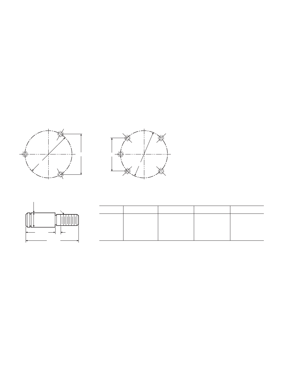
1. Chordal dimensions “A” or “C” must be held
for all chords between pin holes.
2. Drill 27/64 inch diameter holes to a sufficient
depth and tap 1/2-13 UNC-3B one inch min-
imum full threads. Pin holes must be square
with plane of mounting surface and magnet
mounting.
3. Ream .500/.501 to a 3/8 inch depth and to
be concentric with tapped holes.
B
A
C
D
1/2-13 UNC-3A
THDS .
5/16"
1-9/32"
2-1/4"
.6185 Dia.
+.0005
-.0010
Drive Pins Should be Retained
with Sealant
Before installing the drive pins, apply a good
grade of thread sealant such as Loctite
®
, or
equivalent, to the threaded portion only.
Caution must be taken to prevent the sealant
from getting on the bearing surface of the pin.
Tighten all pins securely by inserting an Allen
wrench in the socket provided.
Machining Instructions for Gear, Sprocket, or Pulley
For Sizes 825 through 1525
Unit Size
A
B
C
D
825
3.085 ± .001
3.563 ± .001
1000
4.548 ± .002
5.252 ± .002
1225
4.155 ± .002
5.877 ± .002
1525
6.010 ± .002
8.500 ± .002
- UNIBRAKE NEMA 4 (6 pages)
- UNIBRAKE (8 pages)
- ARC 2000 (16 pages)
- ARC Clutch_ZRC Top Load (18 pages)
- ZRC Clutch_ARC Top Load (18 pages)
- Dairy Cap Chuck (24 pages)
- Dairy Capping Headsets (10 pages)
- Autogap 475 & 650 (4 pages)
- Brushholder Installation (2 pages)
- Autogap 825-1225 (2 pages)
- Electro-Packs EP-170, 250, 400, 500, 825, 1000, 1525 (20 pages)
- Electro-Brake 375, 475, 650, 825, 1000, 1225 (20 pages)
- Electro-Clutch EC-375, EC-475, EC-650, EC-825, EC-1000, EC-1225 (20 pages)
- 5300-101-001 Collector Ring (2 pages)
- 5301-101-010 Collector Ring (2 pages)
- Brushholder Assembly and Mounting Dimensions (2 pages)
- SF_PB 400 (2 pages)
- SF_PB 250 (2 pages)
- Autogap 825-1525 (4 pages)
- Electro-Module EM-50, EM-100, EM-180, EM-210, EM-215 (22 pages)
- FB-375, 475, 650 (14 pages)
- 5200-101-012 Conduit Box Kit (4 pages)
- 5200-101-011 Conduit Box Kit (4 pages)
- 5200-101-010 Conduit Box Kit (4 pages)
- Recommended Electrical Installation Procedure for Warner Electric Clutches and Brakes (2 pages)
- EP-400 Vertical Mounting (2 pages)
- EP-250 Vertical Mounting (2 pages)
- Autogap 500 (4 pages)
- ER 825 and 1225 Normal Duty (16 pages)
- ER 825 and 1225 Heavy Duty (14 pages)
- ERS Electrically Released Brakes (6 pages)
- AT Brakes & Clutches Complete Brake Repair – On the Shaft, Sizes 25, 55, 115 (4 pages)
- AT Brakes (6 pages)
- AT Brake–Major Service Repair Instructions for Sizes 25, 55, 115 (9 pages)
- AT Clutch – Major Service Sizes 25, 55, 115 (12 pages)
- 5162-101-002 Conduit Box Kit (6 pages)
- Electrically Released Permanent Magnet Clutch Compatible Modules (4 pages)
- Electrically Released Motor Brake Module for EM-MBFB and EUM-MBFB (6 pages)
- Electrically Released Brake Module For EM-FBB and EUM-FBB (4 pages)
- Electrically Released Brake ER-375, ER-475, ER-650 (12 pages)
- 5370-101-042 Conduit Box Kit (4 pages)
- Preassembled Clutch_Electrically Released Brake Module (7 pages)
- EUM-50_EUM-100_EUM-180_EUM-210_EUM-215 (16 pages)
- 5370-101-045 Conduit Box Kit (5 pages)