Figure 2 figure 2a – Warner Electric AT Brake–Major Service Repair Instructions for Sizes 25, 55, 115 User Manual
Page 7
7
Warner Electric • 800-825-9050
P-1405 • 819-0325
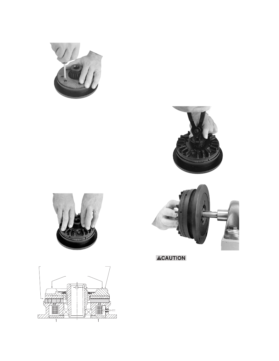
17. Place the brake mounting flange down and
place the armature assembly on the hub. First
engage the spine teeth, then uniformly apply
force by hand, pushing the detent ring over
the spline outside diameter. Now apply force
to the Armature Assembly until the armature
contacts the friction disc. (See Figures 2 and
2A)
Rotate the hub and armature assembly by
hand. There should be no interference.
Install the retaining ring on the hub adjacent to
the armature.
When installing or removing
this or other retaining rings, be sure to
hold the ring with one hand so it will not
spring away, endangering personnel and
property, should the pliers lose their grip
on the ring. Safety glasses should always
be worn when installing or removing
retaining rings.
18. Reinstall the brake on the shaft with the key in
its keyway.
The recessed holes should be facing away
from the magnet body.
Clean the supplied hardware and apply one
drop of Loctite grade AA or equivalent should
be applied to each thread before installation.
Do not allow Loctite to get on friction material
surface.
Fasten with new screws.
Note: Use only the
screws furnished with the kit as others may
damage the brake.
Tighten each screw to 18-22 in.lbs. of torque.
Press Evenly
Approximately
1/16 Airgap
All Ground
Support
Support
Armature
Assembly
Figure 2
Figure 2A