Warner Electric ER 825 and 1225 Heavy Duty User Manual
Page 4
4
Warner Electric • 800-825-9050
P-251 • 819-0121
Figure 2
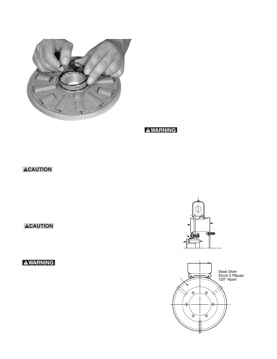
Step 3B:
Turn the assembly over and insert the
retainer ring in the groove. Take care not to bend or
distort retainer ring.
Step 3C:
Turn the assembly over and slide the
armature against the retainer ring.
During steps 4 through 7, handle
the armature/hub assembly by the hub (Figure
3, item 2) only, making sure the armature
(Figure 3, item 3) is as close to the retainer ring
(Figure 3, item 4) as possible. Any movement of
the armature on the splined hub will reduce
available armature travel and may cause
improper setting of the running air gap.
1/16 inch thick steel shims are
recommended for shim stock selection. Do not
use shims thicker than 1/8 inch or you will
shorten brake life by reducing available
armature travel.
Shim stock must be clean and
free of any contamination (oil, grease). Keep
fingers clear of the area between the magnet
and the armature as the armature will be pulled
sharply toward the magnet after the gap is
closed to approximately 1/2 inch.
Step 4:
Place three steel shims 120 degrees apart
on the magnet as shown in Figure 3. Insert the
taper-lock bushing (Figure 3, item 5) into the hub
(Figure 3, item 2).
Slip the armature hub assembly onto the brake
shaft until armature makes contact with shims.
Step 5:
Using a hex wrench, tighten the hub
bushing bolts alternately and evenly until tight.
Using a drift and small hammer, tap lightly at
several points around the circumference of the
taper lock bushing. Repeat this alternate tapping
and re-tightening until the specified torque is
reached and wrench no longer turns the screw after
tapping. Tighten bolts to the following:
Unit
Torque
Bushing Type
ER-825
87 in. lb.
Browning Series H
ER-1225
290 in. lb.
Browning Series Q
Do not attempt to pull the
bushing flange flush with the hub end as
there should be 1/8” to 1/4” clearance
when tightened.
The airgap between armature and magnet must be
.062 to .125 inch. If the airgap is outside of that
range, reposition the armature hub assembly by
repeating steps 1 and 2 of the disassembly
procedure and steps 4 and 5 of the assembly
procedure.
5
1
3
4
2
.062"
Thick
Steel Shims
Friction
Material
Figure 3
1
– Magnet
2
– Splined Hub
3
– Armature
4
– Spiral
Retainer Ring
5
– Bushing