How to order – Warner Electric FB-375, 475, 650 User Manual
Page 12
12
Warner Electric • 800-825-9050
P-237 • 819-0289
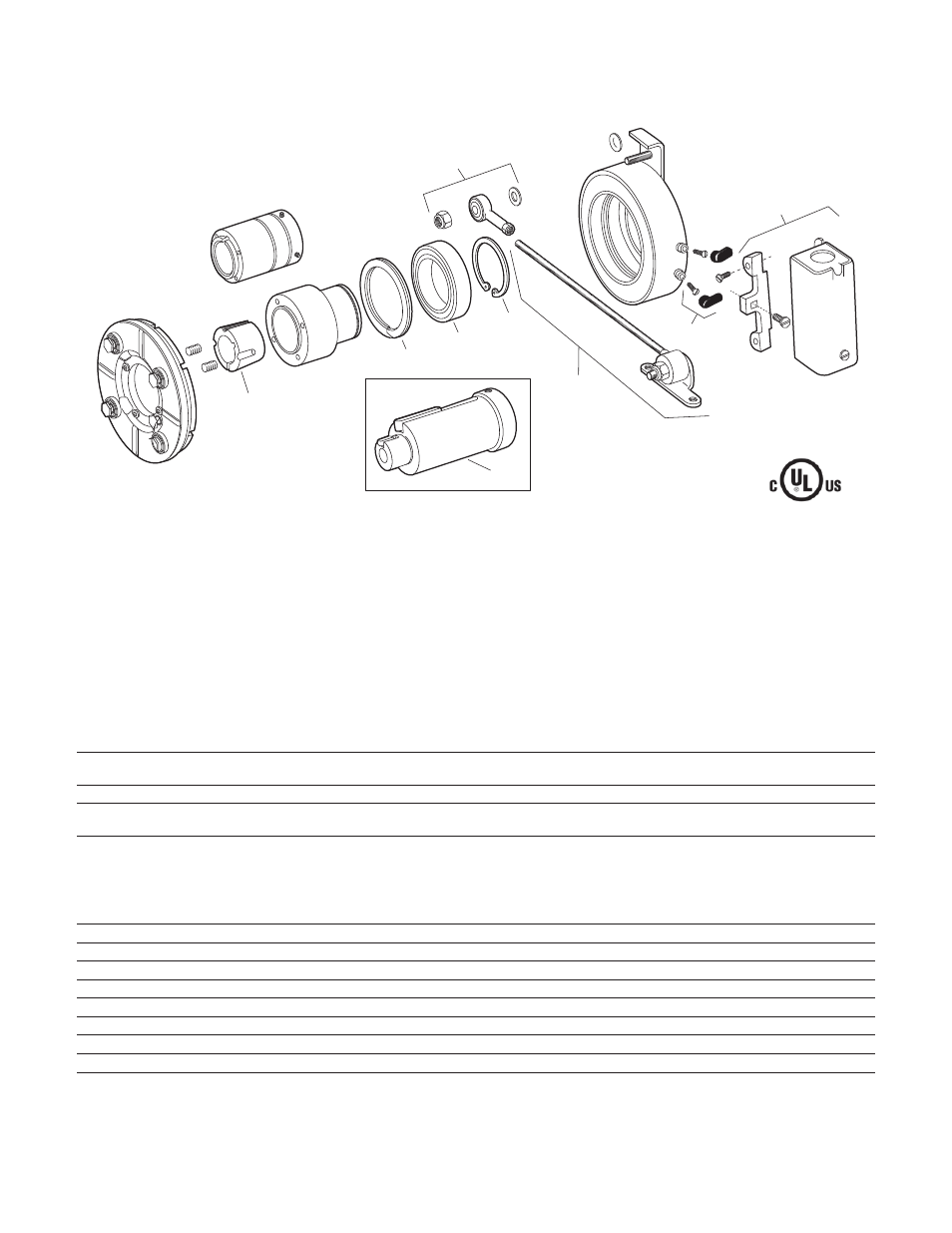
6
1
2
3
4
5
7
8
9
FB-375, FB-475, FB-650
FB-375
FB-475
FB-650
Item
Description
Part Number
Qty
Part Number
Qty
Part Number
Qty
Optional Parts
1
*Bushing
N/A
180-0410 1/2" bore
180-0421 1/2" bore
to 180-0418 1" bore
1
to 180-0435 1-3/8" bore
1
2
Adapter (optional)
1
1
1
5/8" motor shaft
5380-101-005
7/8" motor shaft
5380-101-004
1-1/8" motor shaft
5381-101-003
1-3/8" motor shaft
5382-101-003
1-5/8" motor shaft
5382-101-002
Service Parts
3
Retainer ring
748-0101
1
748-0102
1
748-0104
1
4
Ball bearing
166-0150
1
166-0110
1
166-0104
1
5
Retainer ring
748-0018
1
748-0002
1
748-0004
1
6
Torque arm mount assembly
5380-101-007
1
5381-101-006
1
5382-101-007
1
7
Torque arm rod assembly
5380-112-001
1
5381-112-001
1
5382-112-001
1
8
Terminal accessory
5311-101-001
1
5311-101-001
1
5311-101-001
1
9
Conduit Box
5200-101-010
1
5200-101-010
1
5200-101-010
1
*See page 13 for specific part numbers.
These units, when used with the correct Warner Electric conduit box, meet the standards of UL508 and are listed under guide card #NMTR2, file
#59164. Magnet and armature are not field replaceable.
How to order
1. For thru-shaft mounting, specify bore size. For
FB-475 and FB-650 order bushing separately.
FB-375 does not require a bushing.
2. For motor mounting order adapter separately–
Item 10. Specify the following bore size for the
Electrically Released Brake. This is the bore size
required for mounting the Electrically Released
Brake on the end of the motor adapter.
FB-375
5/8” bore
FB-475
1-1/8” bore
FB-650
1-3/8” bore