Torque adjustments, Wear adjustments – Warner Electric UNIBRAKE NEMA 4 User Manual
Page 4
Brake Leads (B) to Motor Leads (T)
Motor
Voltage
or Separate Power Supply
3 Phase AC
Low Voltage
B1 & B3 to T1 & T7 B2 & B4 to T2 & T8
High Voltage
B1 to T1 B2 to B3 B4 to T2
1 Phase AC
Low Voltage
B1 & B3 to T1 & T3 B2 & B4 to T2 & T4
High Voltage
B1 to T1 B2 to B3 B4 to T4
Separately AC
Low Voltage 115 VAC
B1 & B3 to Line 1 (L1) B2 & B4 to Line 2 (L2)
High Voltage 230 VAC
B1 to Line 1 (L1) B2 to B3 B4 to Line 2 (L2)
Separately DC
24 or 90 VDC
B1 to DC + B2 to DC -
Coils are not polarity sensitive
connections can be reversed.
Gap Chart
No. of Discs
Gap “G”
1
.075 inch
2 or 3
.090 inch
4
Warner Electric • 800-825-9050
P-1701-WE
Determine the voltage of the brake and use the
appropriate wiring instructions below.
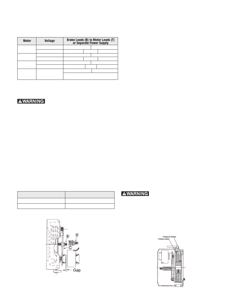
Remove cover, turn both screws “B” equal
amounts in a clockwise direction until air gap (Gap
“G”) from above chart is obtained.
Measurement of air gap should be made at
approximate center of magnet with pressure
applied to armature plate “C” to assure plate is
seated on pivot balls. Failure to adjust for wear
will result in eventual loss of braking torque.
Note: Unequal adjustment of screws “B” will result
in unequal pivot action on balls that will increase
noise and shorten brake life.
Torque Adjustments
Most applications do not require torque
adjustments. Motor brakes are factory set for
rated torque which is maximum torque. To
increase stopping time or reduce torque on 3, 6,
and 10 ft. lb., turn 2 lock nuts “A” an equal amount
counterclockwise to increase spring length. For
the 6, 10, and 15 ft. lb. brakes, one full turn will
reduce torque by about 12-1/2%. The 3 ft. lb.
brake will be reduced in torque by about 8%.
Torque should not be reduced by less than 1/2 of
the rated torque.
If torque is adjusted measure air gap (see wear
adjustment) and verify it is within dimensions from
Gap Chart.
1) Disconnect power brake
before touching any internal part. 2) Any loads
that are held in position by this brake must be
supported before performing any adjustments
or maintenance.
Wear Adjustments
1) Disconnect power brake
before touching any internal part. 2) Any loads
that are held in position by this brake must be
supported before performing any adjustments
or maintenance.
Motor brake discs require periodic adjustment due
to expected wear. On rapid cycling applications
regular inspections should take place, i.e. after
20,000 to 50,000 cycles for the first inspection
and then every 150,000 to 200,000 cycles.
Adjustments should be made to the air gap
between the armature and magnet for continued
brake effectiveness. If an increase in stopping
time is noted adjust brake as follows: