Wiring, Installation – Warner Electric UNIBRAKE NEMA 4 User Manual
Page 3
• Replace pressure plate(s) and friction disc(s)
into housing keeping them in their original
order.
• Remove hand tightened caps screws from head
casting. Replace brake mechanism with coil
into housing and tighten with (2) cap screws,
lock washers and (2) cover hex studs.
• Rotate release lever one or two times to verify
release and assembly of brake is correct.
• Cover will be assembled after brake is wired.
Leads should be twisted and inserted into the
insulation sleeve and routed to conduit port or
openings through back of motor after wiring.
Wiring
Disconnect power before
touching any internal part.
Unibrake magnet coils (AC) are single phase and
dual voltage. These can be wired internal to the
motor. Direct current brake coils must be
separately operated; switch contacts to control the
brake must be different from those used to control
the motor. Normally, motor and brake
contacts must be interlocked.
Determine the voltage of the brake and use the
appropriate wiring instructions below.
Remove cover, turn both screws “B” equal
amounts in a clockwise direction until air gap (Gap
“G”) from above chart is obtained.
3
Warner Electric • 800-825-9050
P-1701-WE
Any mechanism or load held in
position by the brake should be checked to
avoid possible damage or injury to personnel
before brake is released manually.
Installation
This brake is assembled and tested prior to
shipment. It must be disassembled to mount to
your motor and maintain seals to your motor. Do
not make any adjustments to the (2) Wear
Adjustment Screws “B” or (2) Torque Adjust Nuts
“A” during installation to your motor.
Brake disassembly
• Place brake on bench or work surface; remove
cover from brake.
• Remove the two cover hex mounting studs and
brake mechanism with coil. Do not make any
adjustments to the brake mechanism.
• Remove pressure plate(s) and friction disc(s)
keeping them in the original order.
• Remove brake hub.
Be careful not to
damage housing seal.
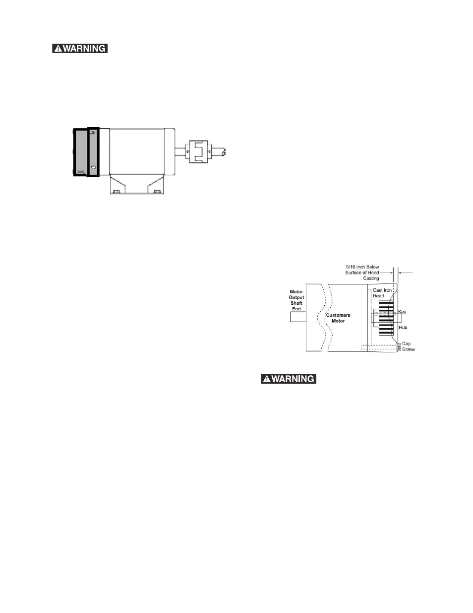
Brake assembly to your motor
• Position brake head casting onto motor
mounting face and secure by hand tightening
(2) 3/8 inch socket head cap screws.
• Attach hub to shaft using key and set screws
provided with Unibrake. Position hub 5/16 inch
below head surface.
Do not damage housing
seal when sliding hub through seal. Tighten
(2) set screws to motor shaft with 55-100 in. lbs.
of torque. Set screws can be accessed through
conduit opening.