Vanguard Auto-Ohm 100_200 s2 User Manual
Page 27
AUTO-OHM 100/200 Series 2 Operating Procedures
27
Rev 3, 2009
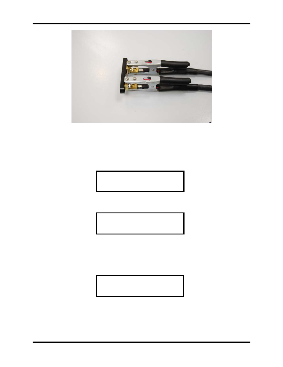
Figure 40.0 Calibration Connection (Combined Leads)
c. During the calibration check the display below (Figure 41.0) shows the current ramping status.
When the test current ramps to 100 %, this display is automatically replaced with the test result
display of Figure 42.0 or Figure 43.0.
Figure 41.0 Current Ramp Message
Figure 42.0 Current-Ramp Error Message
d. If the current did not ramp properly (test failed) the CUR RAMP ERROR display above
(Figure 42.0) will appear. Press the control knob to abort the test (restart the CAL CHECK
when the problem is corrected).
Figure 43.0 Current Ramp Circuit Pass Message
e. The above status display indicates that the current ramped properly. The status displays of
Figure 44.0 through Figure 46.0 show for about 3 seconds each as each test is performed and
passed. If any test fails, the status display will stop at the failed function and indicate “FAIL” on
CURRENT RAMP CKT
“PASS”
CUR RAMP ERROR!
CHECK CABLES
CUR RAMP: 20%