Xcite/io installation instructions, 3 installation - mounting, Connect digital inputs – TREND XCITE_IO User Manual
Page 4: Connect thermistor inputs, Continued), Digital input i/o modules only), 14 to 20 awg) - cu only, Volt free contact input, Open collector type input 24 vac input, Logic input
XCITE/IO
Installation Instructions
XCITE/IO Standard I/O Module Installation Instructions TG200627 Issue 2/E 06/12/07
4
3 Installation - Mounting
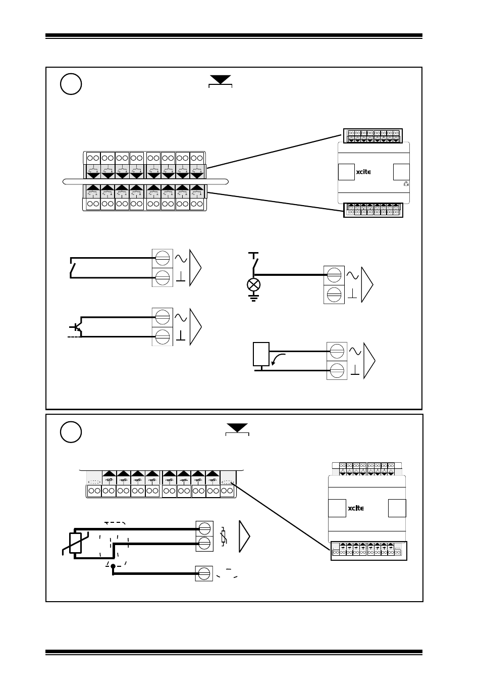
(continued)
Connect Digital Inputs
7
Trend TP/1/1/22/HF/200 (Belden 8761) cable recommended for all inputs
1 2
1
3 4
2
5 6
3
7 8
4
9 10
5
11 12
6
13 14
7
15 16
8
17 18 19 20 21 22
13
14
15
16
9
10
11
12
23 24
25 26 27 28 29 30 31 32
(Digital input I/O modules only)
17 18 19 20 21 22
13
14
15
16
9
10
11
12
23 24
25 26 27 28 29 30 31 32
XCITE/IO/16DI channels 1 to 16, ../8DI channels 1 to 8
EN61010:2001 MEASUREMENT CATEGORY 1.
Separate from 230 Vac supply by double or reinforced insulation
Cable size 0.5 to 2.5 mm
2
(14 to 20 AWG) - Cu only
N
1 2
1
3 4
2
5 6
3
7 8
4
9 10
5
11 12
6
13 14
7
15 16
8
N
Volt free contact input
N
0 V
Open collector type input
24 Vac input
N
24 Vac ±20%
Load
Logic input
N
0 V
3 m A
e . g .
T T L
C M O S
logic high = 5 to 50 V
logic low = sink >3 mA
Note that logic low on input
produces ON state in IQ3
16DI
Connect Thermistor Inputs
8
Trend TP/1/1/22/HF/200 (Belden 8761) cable recommended for all inputs
(Thermistor input I/O modules only)
XCITE/IO/8DI/8TI channels 9 to 16
N
17 18
17 18 19 20
19 20 21 22
21 22
13
14
15
16
9
10
11
12
23 24
23 24
25 26
25 26 27 28
27 28 29 30
29 30 31 32
31 32
T
T
T
T
T
T
T
T
1
2
1
3
4
2
5
6
3
7
8
4
9
10
5
11 12
6
13 14
7
15 16
8
0V
N
T
17 18
17 18 19 20
19 20 21 22
21 22
13
14
15
16
9
10
11
12
23 24
23 24
25 26
25 26 27 28
27 28 29 30
29 30 31 32
31 32
T
T
T
T
T
T
T
T
1
2
1
2
1
3
4
3
4
2
5
6
5
6
3
7
8
7
8
4
9
10
9
10
5
11 12
11 12
6
13 14
13 14
7
15 16
15 16
8
8DI/8TI