Check module, Continued) – TREND XCITE_IO User Manual
Page 13
XCITE/IO Standard I/O Module Installation Instructions TG200627 Issue 2/E 06/12/07
13
Installation Instructions
XCITE/IO
4 Installation - Configuration
(continued)
4 5 6
2
7 8 9
3
10 11 12
4
13 14 15
5
16 17 18
6
19 20 21
7
22 23 24
8
25 26 27
9
28 29 30
10
+ 0
+ 0
+ 0
+ 0
+ 0
+ 0
+ 0
+ 0
+ 0
1 2 3
1
+ 0
0 V
24 V
24 V
34 35 36
12
37 38 39
13
40 41 42
14
A
31 32 33
P
11
43 44 45
15
46 47 48
16
100-240 V
OK RX
P 0
P 0
P 0
P 0 P 0
P 0
24
V
P
13 14 15
5
P 0
16 17 18
6
P 0
19 20 21
7
P 0
22 23 24
8
P 0
1 2 3
1
+ 0
4 5 6
2
+ 0
7 8 9
3
+ 0
10 11 12
4
+ 0
24
V
P
13 14 15
5
P 0
16 17 18
6
P 0
19 20 21
7
P 0
22 23 24
8
P 0
1 2 3
1
+ 0
4 5 6
2
+ 0
7 8 9
3
+ 0
10 11 12
4
+ 0
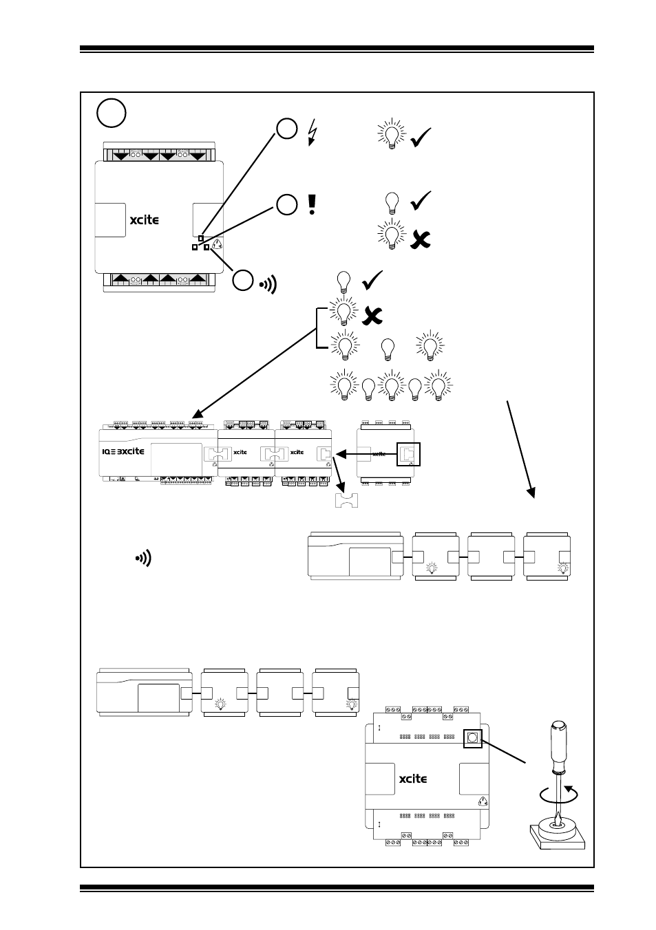
13
Check Module
1 2 3
1
+ 0
4 5 6
2
+ 0
7 8 9
3
+ 0
10 11 12
4
+ 0
8
+ 0
7
+ 0
6
+ 0
13 14 15
5
+ 0
16 17 18 19 20 21
22 23 24
a
b
c
(power)
(green)
(watchdog)
(red)
(I/O bus)
(red)
1s
1s
I/O Module Faulty
I/O bus comms fault
Address=0 (disabled)
or Address clash
fast
Address = X
= X
= X
disconnect
Switch off power
Disconnect farthest I/O module
Move terminator
Switch on power
Check
(I/O) light
Repeat to isolate faulty module
Replace faulty module or
connection
I/O bus fault (check short circuit, Data
Hi or Data Lo to either power line)
Repeat step 8 above until LED extinguishes
Note that the if the I/O module address is changed,
it also needs to be changed in the IQ3xcite
configuration file (i.e. SET, Device-I/O Setup)
before the module can be used- see IQ3xcite
installation Instructions TG200626 section 4
step 22.
Address = X
= X
= X
if address clash