Xcite/io installation instructions, 4 installation - configuration, Set i/o address – TREND XCITE_IO User Manual
Page 12: Replace covers, Switch on, Check for digital input misconnection, Configure iq3xcite controller, Ab c, Continued)
XCITE/IO
Installation Instructions
XCITE/IO Standard I/O Module Installation Instructions TG200627 Issue 2/E 06/12/07
12
4 Installation - Configuration
(continued)
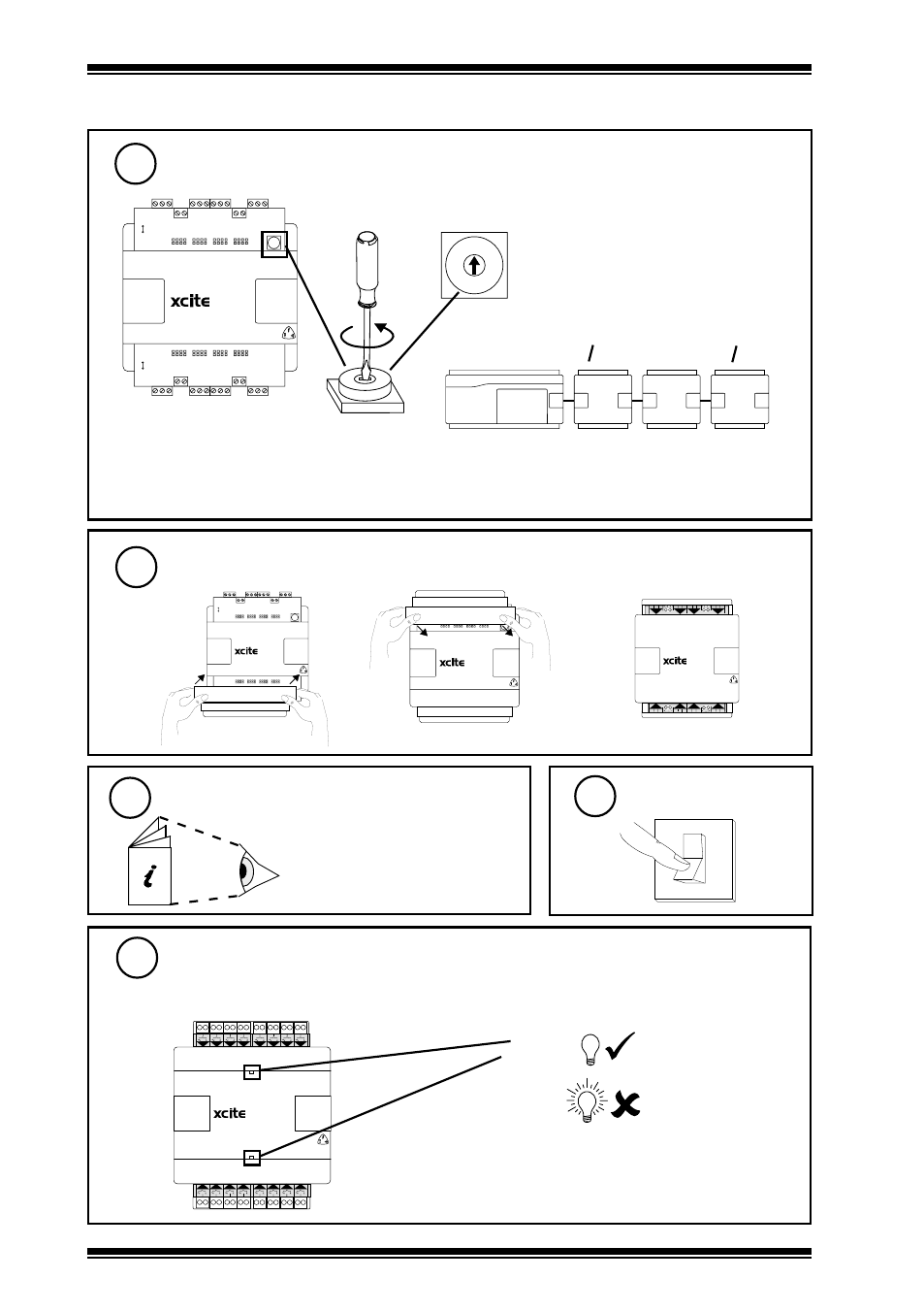
8
Set I/O Address
012
3
4
5
678
9A
B
C
D
EF
Address = 1, 2, 3, 4, 5, 6, 7, 8,
9, A, B, C, D, E, F
(Address 0 = disabled)
Address = X
= X
= X
= X
Note that the I/O module needs to be set up (i.e. SET, Device-I/O Setup); the module ID (address),
and its type need to be entered before the module can be used- see IQ3XCITE Installation
Instructions TG200626 section 4 step 22.
9
Replace Covers
a
b
c
1 2 3
1
+ 0
4 5 6
2
+ 0
7 8 9
3
+ 0
10 11 12
4
+ 0
8
+ 0
7
+ 0
6
+ 0
13 14 15
5
+ 0
16 17 18 19 20 21
22 23 24
11
O
I
Switch On
12
Check for Digital Input Misconnection
(Digital input I/O modules only (-/16DI, /8DI, /8DI/8TI) with ac input)
1 2
1
3 4
2
5 6
3
7 8
4
9 10
5
11 12
6
13 14
7
15 16
8
17 18 19 20 21 22
13
14
15
16
9
10
11
12
23 24
25 26 27 28 29 30 31 32
channels 1 to 8
channels 9 to 16
Input
Polarity
(red)
Check each ac input connection is
either isolated from ground or has
correct side groundeded with respect
to IQ3 ground
16DI
10
IQ3xcite Installation
Instructions - TG200626,
Configuration, section 4 steps 1
to 26
Configure IQ3xcite Controller