Xcite/io installation instructions, 3 installation - mounting, Terminate i/o bus – TREND XCITE_IO User Manual
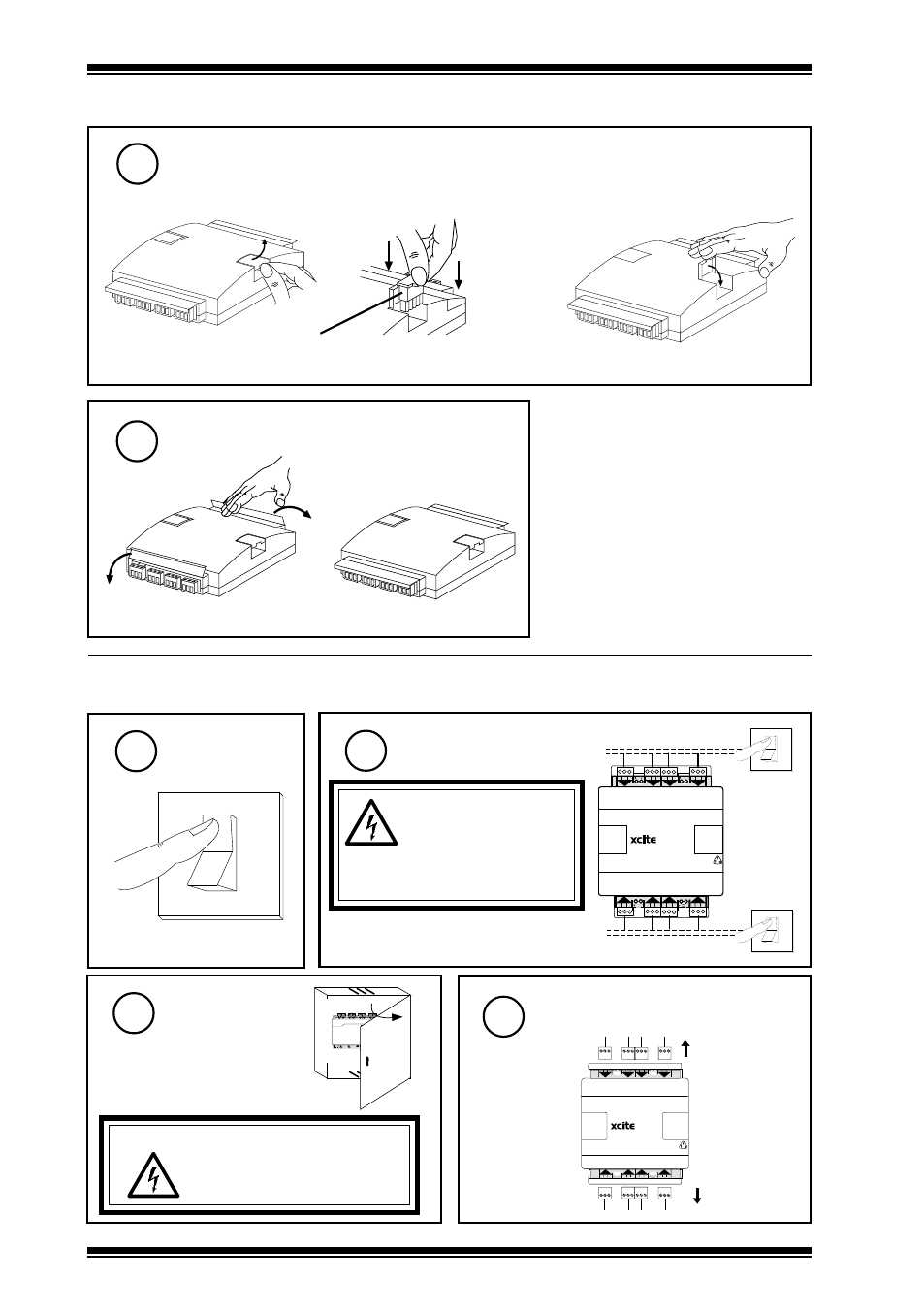
Page 10: Switch off, Isolate i/o, Open panel, Disconnect i/o, Continued), Open flap, Plug in terminator
XCITE/IO
Installation Instructions
XCITE/IO Standard I/O Module Installation Instructions TG200627 Issue 2/E 06/12/07
10
3 Installation - Mounting
(continued)
14
Terminate I/O Bus
Open flap
a
Plug in terminator
b
on I/O module at opposite end of I/O bus from main IQ3xcite controller
XCITE/TERM terminator (supplied with controller)
(XCITE/TERM/5, pack of 5 available separately)
15
Close flap
c
Lower I/O Terminal Covers
4 Installation - Configuration
O
I
Switch Off
1
Isolate I/O
2
WARNING: The
connecting leads may
be connected to
supplies. Isolate before
touching.
also isolate I/O of controller and any
adjacent I/O modules
O
I
1 2 3
1
+ 0
4 5 6
2
+ 0
7 8 9
3
+ 0
10 11 12
4
+ 0
8
+ 0
7
+ 0
6
+ 0
13 14 15
5
+ 0
16 17 18 19 20 21
22 23 24
O
I
Open Panel
3
A
0 V
24 V
24 V
34 35 36
12
37 38 39
13
40 41 42
14
A
31 32 33
P
11
43 44 45
15
46 47 48
16
100-240 V
OK RX
P 0
P 0
P 0
P 0 P 0
P 0
4 5 6
2
7 8 9
3
10 11 12
4
13 14 15
5
16 17 18
6
19 20 21
7
22 23 24
8
25 26 27
9
28 29 30
10
+ 0
+ 0
+ 0
+ 0
+ 0
+ 0
+ 0
+ 0
+ 0
1 2 3
1
+ 0
WARNING: Opening the panel may
expose dangerous voltages.
417-IEC-5036
Disconnect I/O
4
1 2 3
1
+ 0
4 5 6
2
+ 0
7 8 9
3
+ 0
10 11 12
4
+ 0
8
+ 0
7
+ 0
6
+ 0
13 14 15
5
+ 0
16 17 18 19 20 21
22 23 24
a
b