TREND IQ23x User Manual
Page 24
IQ23x
Installation Instructions - Replacing IQ131
IQ23x Series Controllers Installation Instructions TG200539 Issue 1/A 26/3/02
6 - 4
18
Set Network Baud Rate to previous
as noted in step 9 above - see Sheet 2 step 6
6 Replacing an IQ131 with an IQ233
(continued)
19
Set Network Address to previous
as noted in step 9 above - see Sheet 2 step 9
20
Remove Cover
see Sheet 2 step 6
21
Link Input Channels
as noted in step 9 above - see Sheet 2 step 9
22
Fit Link Headers
to channels as noted in step 9 above
- see Sheet 2 step 10
23
Replace Cover, Switch On,
Check Controller, Check Network
- see Sheet 2 steps 11 to 14
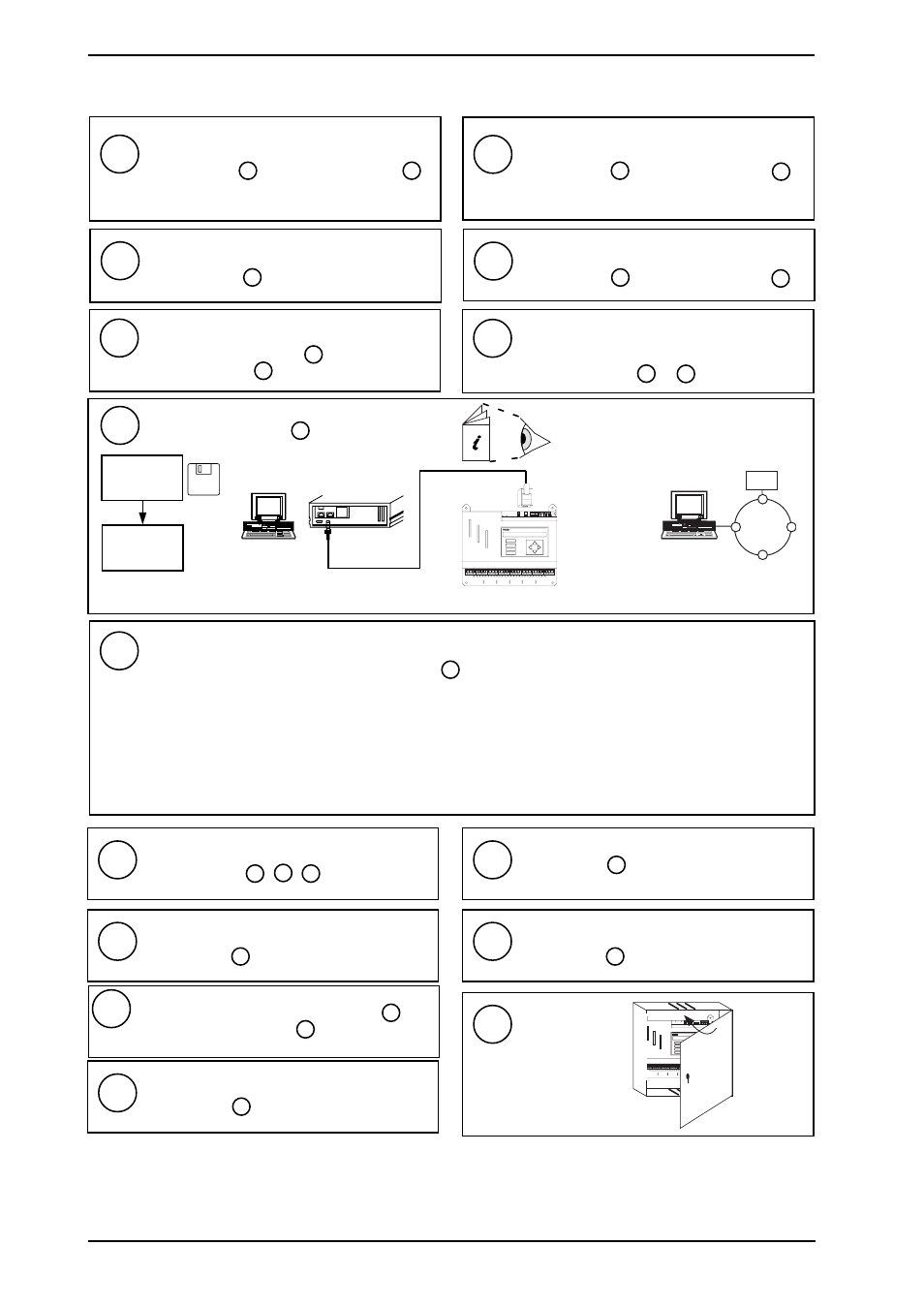
I Q 2 3 3
Download Strategy file
24
WupDn Manual TE200162
PowerTool Manual TE200163
OR
R X
T X
O K
A
D
D P
C
B
1
2
8
4
16
32
64
1K
2
9K
6
19
K
2
A D D R E S S
B A U D
9 'D type'
Female
Cable/EJ101442
RJ11
IQ233
WupDn or
PowerTool
IQ233
X.IQF
set time, date, day of week
25
Make IQ2xx Changes
26
Test Inputs, Test Outputs, Backup
see Sheet 2 step 16 17 18
27
Connect External Display Panel
28
Connect Local Supervisor
if noted in step 6 - see Sheet 3 section 3.2
29
Connect External NDP
if noted in step 6 - see Sheet 3 section 3.3
31
Connect Internal Node
if noted in step 9 - see Sheets 8, 9
32
Close Panel
1 2 3 4 5 6 7 8 9 1 0
R X
T X
O K
A D D R E S S B A U D
S W 4
A
D
D P
C
B
J 1 6
D e v B
J 1 5
D e v A
previously saved in step 2 above
if noted in step 6 - see Sheet 3 section 3.1
either upload to SET and make changes,
or change in configuration mode - see Sheet 2 step 15 .
Loop Reschedule Time
:
Multiply by 5 and re-enter
Sensor Scaling Mode 1
: If sensor outputs a voltage signal, and scaling mode 0, linear is being used, multipy T and B by 2 and re-enter.
Sensor Scaling Mode 2
: If scaling mode 2 (linearise thermistor volts) is used, change it to sensor scaling mode 3 (linearise volts).
Shared Labels
:
Set up digital input labels. (Copy from sensor channel of same number if appropriate).
Internal Sensors
:
If an internal sensor is used in internal digital mode, bit 506,1 should be set to one
Internal Digitals
:
If internal digitals in the range 17 to 20 are used, the strategy should changed bymoving them to
an area of unused internal digitals on IQ233 (digital input 21 onwards).
30
Set Baud Rate of Supervisor
if 1k2 supervisor baud rate noted in step 9 , and
supervisor connected in step 29 above, set baud rate
of supervisor to 9k6