Check setup, If node fitted remove node card, Remove iq111 – TREND IQ23x User Manual
Page 23: Replace with iq233, Connect power, Connect network, Connect inputs, Connect outputs, Connect auxiliary supply
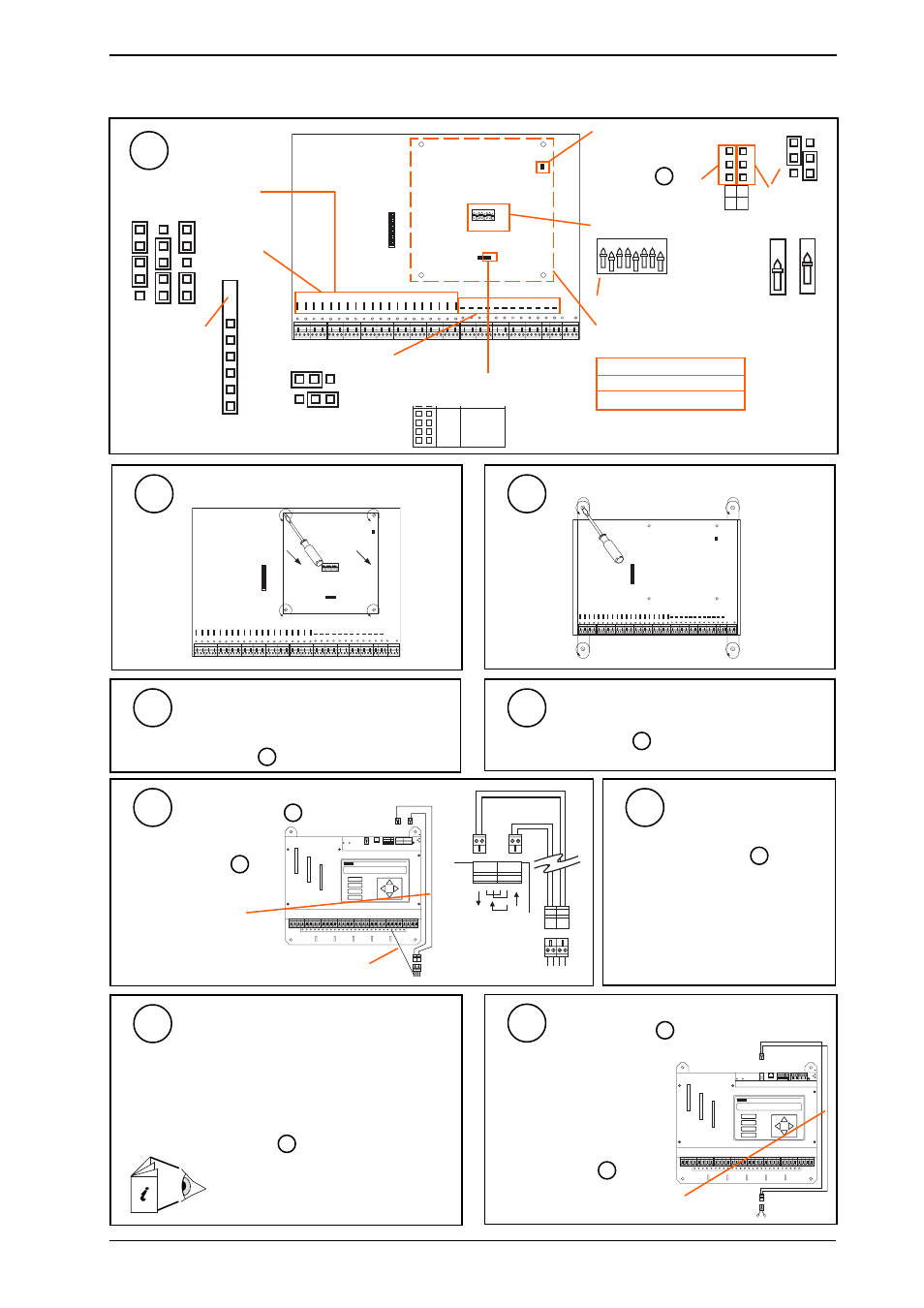
Installation Instructions - Replacing IQ131
IQ23x
IQ23x Series Controllers Installation Instructions TG200539 Issue 1/A 26/3/02
6 - 3
A
D
D P
C
B
R X
T X
O K
1
2
8
4
16
32
64
1K
2
9K
6
19
K
2
A D D R E S S
B A U D
Check Setup
9
6 Replacing an IQ131 with an IQ233
(continued)
O F F
1 2 3 4 5 6 7 8 D U M B
N O R M
1
2
4
8
1 6
3 2
6 4
Note network baud rate
settings on integral CNC
Is a node fitted?
new (TMN type) board or not?
Check output link settings
V
1
1 9 K 2
9 K 6
4 K 8
1 K 2
N e t w o r k
Note input link settings
1
V
D
Check for
Link Headers
C
Link Header type
LK/A, B, C, D,
E, F, 0
?
If Node Fitted Remove Node Card
10
Remove IQ111
11
O F F
1 2 3 4 5 6 7 8 D U M B
N O R M
1
2
4
8
1 6
3 2
6 4
Replace with IQ233
Same centres
If mounting bars were not used, redrill - see
Sheet 1 step 3
12
Connect Power
Plug in power lead - see
Sheet 1 step 4
13
Connect Network
14
Connect Inputs
Signal leads should plug in
channel for channel - see
Sheet 1 step 6
15
see Sheet 1 step 5
2 off 2 wide network
extension cables
provided in
KIT/IQ23x/UPGRADE
screen
Connect Outputs
16
Note: Early IQ131s had single part input
connectors so will require terminals to
be wired.
Channels previously linked as current (I) will need:
either (a) Replace SRMI by SRMV or (2SRM for pair of
channels)
or (b) Add 2VID for each pair of channels
Otherwise signal leads should be plugged in channel for
channel - see Sheet 1 step 7
2VID Data Sheet TA101135A
SRMV Installation Instructions 91-2853
2SRM Installation Instructions TG103210
A
D
D P
C
B
R X
T X
O K
1
2
8
4
16
32
64
1K
2
9K
6
19
K
2
A D D R E S S
B A U D
Connect Auxiliary Supply
17
see Sheet 1 step 8
2 wide extension cable provided
in KIT/IQ23x/UPGRADE
0
24
0 24
CNC, CNC2, PNC, PNC2
MNC, TMN
ANC, AND, XN28, XNC
if used - see step 6 above
if used - see step 7 above
Note that a CNC used to connect a local supervisor or
NDP to the network may be discarded
Note supervisor
baud rate settings
after removing node
card step 10
Check network address on integral CNC
O F F
1 2 3 4 5 6 7 8 D U M B
N O R M
1
2
4
8
1 6
3 2
6 4
1
O F F
1
O F F
NOT
SET
SET
e.g Address = 2 + 16 = 18
L
L
H
H
N
S
1k2 9k6
Node
Supervisor
BAUD
R + R - T + T -
+
-
R + R - T + T -
+
-
+
- +
-
R +
R -
T +
T -
Note: Rewire +24 Vdc from
24 Vdc terminal on IQ131 into one
terminal of 2 way extension
connector and rewire 0 V from
adjacent 0 V terminal on IQ131 to
other terminal of 2 way extension
connector.