TREND IQ23x User Manual
Page 19
Installation Instructions - Replacing IQ111+
IQ23x
IQ23x Series Controllers Installation Instructions TG200539 Issue 1/A 26/3/02
5 - 3
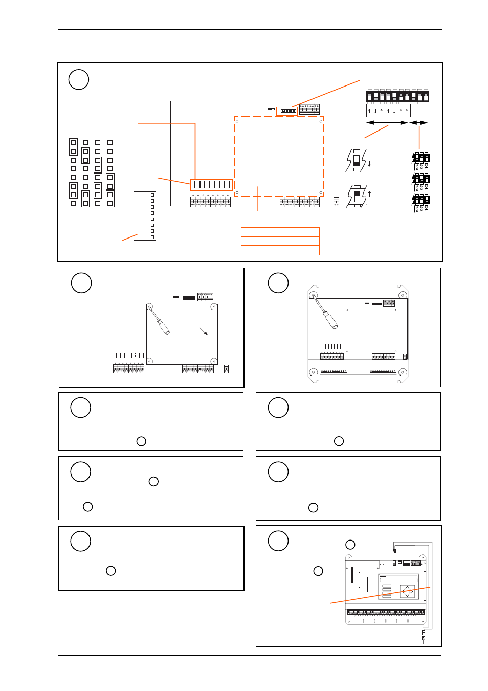
Check Setup
9
5 Replacing an IQ111+ with an IQ231
(continued)
1 2 3 4 5 6 7 8 9 1 0
Note address
Note baud rate settings
Is a node fitted?
new (TMN type) board or not?
Note input link settings
1
V
D
T
Check for
Link Headers
1 5 V
Link Header type
5V, 15V, 10mA
?
If Node Fitted Remove Node Card
10
Remove IQ111+
11
1 2 3 4 5 6 7 8 9 1 0
1 2 3 4 5 6 7 8 9 1 0
Replace with IQ231
Same centres
If mounted in small box (380 x 380 x 80 mm) using
semi-circular cutout fixings, redrill - see
Sheet 1 step 3
12
Connect Power
Check mains supply can provide 60 VA.
Plug in power lead - see
Sheet 1 step 4
13
Connect Network
if used - see step 6 above
14
Connect Inputs
15
Connect Outputs
16
Signal leads should be plugged in channel for channel - see
Sheet 1 step 7
A
D
D P
C
B
R X
T X
O K
1
2
8
4
16
32
64
1K
2
9K
6
19
K
2
A D D R E S S
B A U D
Connect Auxiliary Supply
17
see Sheet 1 step 8
2 wide extension cable
provided in
KIT/IQ23x/UPGRADE
0
24
0 24
CNC, CNC2, PNC, PNC2
MNC, TMN
ANC, AND, XN28, XNC
if used - see step 6 above
Note that a CNC used to
connect a local supervisor or
NDP to the network may be
discarded
Network connections should plug in directly - see Sheet 1
step 5
1
2
8
4
16
32
64
1K
2
9K
6
19
K
2
B A U D
A D D R E S S
O N
19k2 baud
9k6 baud
1k2 baud
e.g.
Address = 2 + 16 = 18
SET
NOT SET
Signal leads should plug in channel for channel - see
Sheet 1 step 6