Jitter transfer function calibration, Qphy-sata software option – Teledyne LeCroy QPHY-SATA User Manual
Page 45
QPHY-SATA Software Option
915745 Rev
G
45
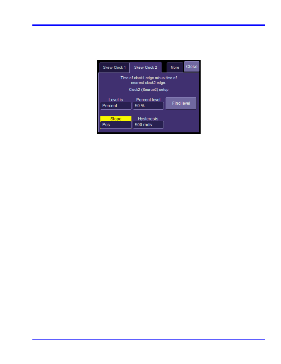
Alternately, we clearly could have not inverted C3 and instead selected the Skew clock 2 tab in the P1 parameter
menu and set the oscilloscope to look for negative edges on the second input (C3). However, it is somewhat
agreed that the previous procedure looks much more aesthetically pleasing from the display as it shows C2 and
C3 with the same polarity.
Figure 27. The Skew parameter right side dialog, Skew clock 2 tab, showing default setup
Jitter Transfer Function Calibration
The SATA specification requires that a reference clock is used for all jitter measurements. The reference clock is
recovered from the data using a phase-locked loop (PLL). The PLL tracks small phase changes in the waveform.
Therefore, the recovered clock will have less jitter at lower frequencies than the original data. This difference is
called the Jitter Transfer Function (JTF). The SATA specification revision 3.0 defines the exact Jitter Transfer
Function that the oscilloscope, or any jitter measurement device, must apply to a signal when recovering the
clock. LeCroy oscilloscopes have two variables that control the PLL transfer function. Natural frequency controls
the cutoff frequency of the PLL, and critical damping controls the peaking of transfer function. QualiPHY
configurations include settings for both variables, as described in the QPHY-SATA Variables section. The SATA-IO
has developed a procedure called the Jitter Measurement Device Calibration Procedure for verifying the jitter
transfer function. Please consult the SATA_PHY_MOI_LeCroy_PHY_TSG_OOB Method Of Implementation for
the procedure specific to LeCroy oscilloscopes.
§ § §