Phy oob requirements, Figure 14. signal detection threshold device setup, Qphy-sata software option – Teledyne LeCroy QPHY-SATA User Manual
Page 35
QPHY-SATA Software Option
915745 Rev
G
35
IsoBER function. Then the vertical opening is measured at the center of the
IsoBER.
TSG-16
– Gen3 TX AC Common Mode Voltage
This test measures the AC Common Mode Voltage for products running at 6.0Gb/s. It is measured using HFTP.
The measurement is made in the frequency domain by examining the peaks at the fundamental and second
harmonic frequencies.
PHY OOB Requirements
The PHY OOB Requirements (OOB) group of tests includes parameters from Table 34 in the SATA specification,
revision 3.0. There are a total of 7 tests defined in this group. There are two types of Out of Band (OOB) patterns:
COMRESET/COMINIT and COMWAKE. Both consist of 6 bursts of data.
See the SATA_PHY_MOI_LeCroy_PHY_TSG_OOB Method of Implementation for detailed test procedures.
OOB-01
– Signal Detection Threshold
This test verifies the product responds to OOB signals above the minimum detection threshold and does not
respond to OOB signals below the level at which it should not detect OOB. The test is conducted by sending an
OOB waveform from a signal generator to the product under test and checking if it responds using the
oscilloscope.
When using the PeRT
3
the result is tested by the PeRT
3
and not by the oscilloscope.
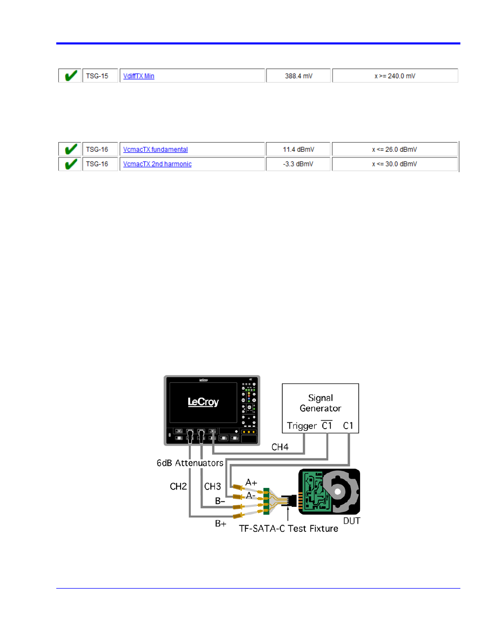
The following graphic illustrates the setup for a device without the PeRT
3
:
Figure 14. Signal Detection Threshold device setup
The signal generator is set to output a COMRESET at regular intervals. The trigger output is used to indicate
when a COMRESET has been sent. When the device responds to COMRESET it sends COMINIT as follows: