Teledyne LeCroy ZS2500 User Manual
Page 19
Operator’s Manual
Where Ctotal is the combined probe and circuit capacitance and Rtotal is
combined circuit and probe resistance.
For a setup where Ct = 0.9 pF and a source resistance is 250
Ω, the measured
rise time will be 0.495 ns, which will correspond to a bandwidth of 909 MHz,
assuming no inductive loads.
t
rise
= 2.2 x 0.9 x 10-
12 x 250 Ω = 0.495 ns
Parallel combination of 250
Ω and 1 MΩ is still 250 Ω
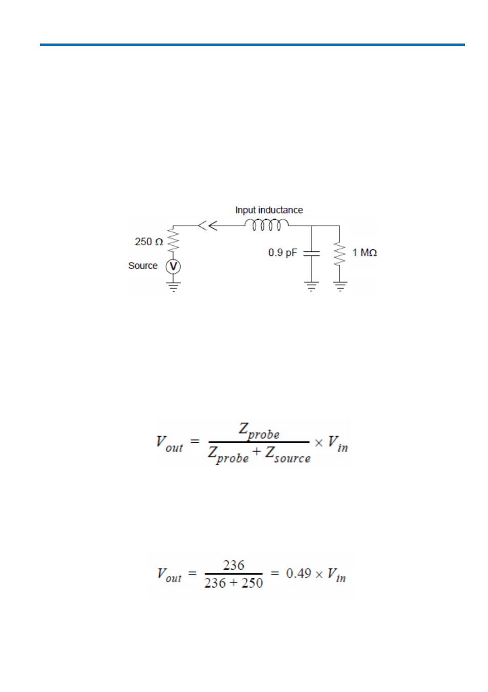
Example Probe input equivalent circuit. Actual diagrams p.14.
To illustrate the effect of capacitive loading at higher frequencies:
At a frequency of 750 MHz the reactance of the 0.9 pF capacitance is 236
Ω, and
at 1.0 GHz the reactance has been lowered to 177
Ω.
If, at a given frequency, the source impedance is large with respect to the input
impedance, a measurable reduction in the output signal amplitude may occur.
where Zprobe is the probe’s input impedance and Zsource is the source
impedance.
For example: At 750 MHz, where the probe input impedance has reduced to 236
Ω, and a source resistance of 250 Ω the probe output amplitude is reduced to:
924282-00 Rev A
13