High frequency measurements, Probe input loading, Inductive loading (lead length) – Teledyne LeCroy ZS2500 User Manual
Page 17
Operator’s Manual
High Frequency Measurements
Probe Input Loading
When you touch a probe to the circuit under test, the probe will affect your
measurement because of the probe’s input impedance introduced into the
circuit. All probes present resistive, capacitive and inductive loading.
Inductive Loading (Lead Length)
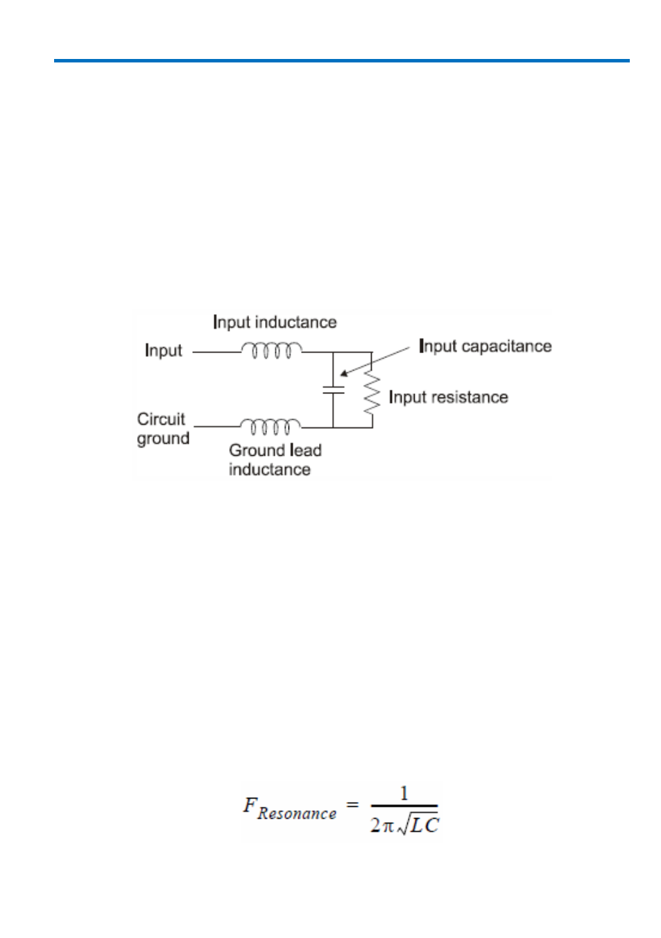
A significant element in this circuit is the inductance shown in the input ground
leads of the oscilloscope probe.
Example probe input equivalent circuit. Actual diagrams p.14.
The ground lead is the primary return path for the current resulting from the
input voltage acting on the probe’s input impedance. The ground lead and input
lead inductances act with the probe’s input capacitance to form series L-C
network. The impedance of a series LC network drops dramatically at its
resonant frequency. This is the cause of the "ring" we often see after the leading
edge of pulses in measured waveforms.
This effect is referred to as ground lead corruption. Because it is impossible to
eliminate either the L or C from this circuit, the method to improve waveform
fidelity is to raise the resonant frequency beyond the bandwidth of interest in
the measurement.
The resonant frequency of a simple LC circuit can be represented by:
924282-00 Rev A
11