Heat sinking, Ac line and motor connections, 8installation – LEESON Chassis Mount Regenerative Control: 175721.00 User Manual
Page 14
8
Installation
Heat sinking
Model 175721.00 requires an additional heat sink, p/n 175722,
when the continuous armature current is above 7 ADC. Model
175720.00 has sufficient heat sinking in its basic configuration.
Use a thermally conductive heat sink compound (such as Dow
Corning
®
340 Heat Sink compound) between the drive chassis
and the heat sink surface for optimum heat transfer.
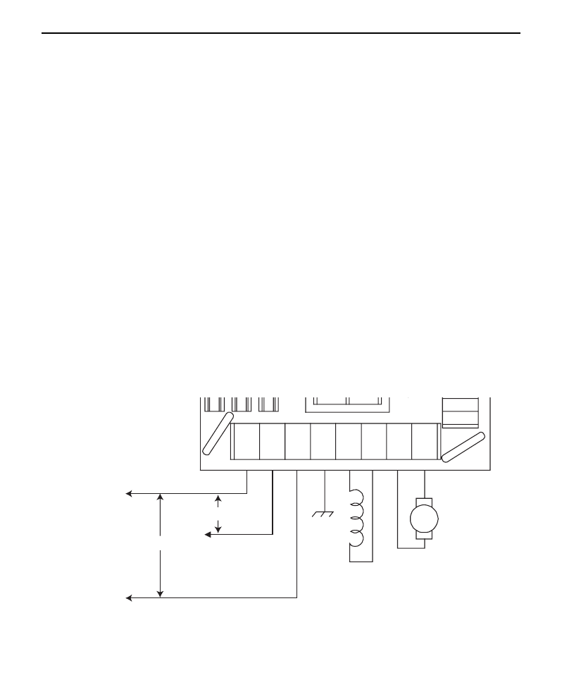
AC line and motor connections
Use 12 AWG or 14 AWG standard wire for connecting the
line and the armature. Use 16 AWG or 18 AWG standard wire
when connecting the field of a shunt-wound motor. Strip the
wire insulation 0.25 inches (6 mm). See Figures 4 and 5 for
AC line (115 VAC or 230 VAC) and motor connections to
chassis and cased drives.
Figure 4. Chassis Drive Connections
AC INPUT
VOLTAGE
115 VAC
230 VAC
L1
GND
F1
F2
A2
A1
L2
115V
C505
TB502
TB501
SW501
C503
IC502
S3
S2
L2
230V
C504
FIELD OUTPUT
For shunt wound
motors only. See field
output section for details.
MOTOR