LEESON Micro Series Compact Inverters User Manual
Page 59
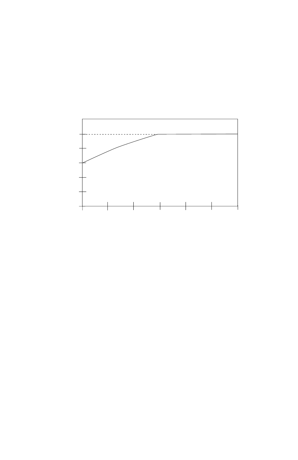
The “speed-compensated” thermal overload circuit offers additional protection from high load conditions
at low speeds, where motor cooling is often less effective (e.g., motors with shaft-mounted fans). As seen on
the diagram below, the drive reduces the allowable continuous output current when operating at frequencies
less than 30 Hz.
Example 2:
A 480 Vac, 20 HP drive is operating a motor at 10 Hz. From the diagram, a drive operating at
10 Hz can deliver about 75% of its output current rating continuously. A 480 Vac, 20 HP drive’s output
current rating is 27 Amps . Therefore, the drive would be able to operate continuously at 20 Amps . The
drive would also be able to deliver 150% of that value (30 Amps) for one minute before tripping into an
OVERLOAD fault .
The “speed compensated” thermal overload is the factory default and should be used in applications where
the motor does not normally experience high loads at low speeds for extended periods of time.
NOTE 1:
The above diagram is based on a MOTOR OL setting of 100% . For lower MOTOR OL settings,
reduce the % CURRENT values by the same percentage. For example, if MOTOR OL is set to 75%, reduce
the % CURRENT values by 25% . Therefore, the curve shifts down, but the shape of the curve remains the
same .
The “non-compensated” thermal overload circuit allows 100% current continuously, and 150% current
for one minute, at all speeds. In the example above, the motor operating at 10 Hz without
“speed-compensated” protection would be allowed to operate continuously at 27 Amps, and could draw
40 .5 Amps for one minute before tripping . Without sufficient motor cooling, this can result in motor
failure due to overheating .
The “non-compensated” circuit is selected by setting Parameter 22 - TORQUE to CT/NOCMP. The
“non-compensated” setting should only be used in applications where the motor is properly cooled at all
speeds, or the motor manufacturer has approved the motor for full-load operation at low speeds .
NOTE 2:
The operation of the motor thermal overload circuit is affected by the setting of Parameter 34 -
LOAD MLT .
57
NON-COMPENSATED
SPEED COMPENSA
TED
100
80
60
40
20
10
20
30
40
50
60
FREQUENCY (Hz)
MAXIMUM CONTINUOUS OUTPUT CURRENT (%
)