0 installation – LEESON Micro Series Compact Inverters User Manual
Page 24
7.0 INSTALLATION
DRIVES MUST NOT BE INSTALLED WHERE SUBJECTED TO ADVERSE ENVI-
RONMENTAL CONDITIONS! DRIVES MUST NOT BE INSTALLED WHERE
SUBJECTED TO: COMBUSTIBLE, OILY, OR HAZARDOUS VAPORS OR DUST;
EXCESSIVE MOISTURE OR DIRT; STRONG VIBRATION; EXCESSIVE AMBIENT
TEMPERATURES . CONSULT LEESON FOR MORE INFORMATION ON THE
SUITABILITY OF A DRIVE TO A PARTICULAR ENVIRONMENT .
The drive should be mounted on a smooth vertical surface capable of safely supporting the unit without
vibrating . The LCD display has an optimum field of view, this should be considered when determining the
mounting position .
Chassis models must be installed in an electrical enclosure which will provide complete mechanical
protection and maintain uniform internal temperature within the drive’s ambient operating temperature
rating. All drive models MUST be mounted in a vertical position for proper heatsink cooling.
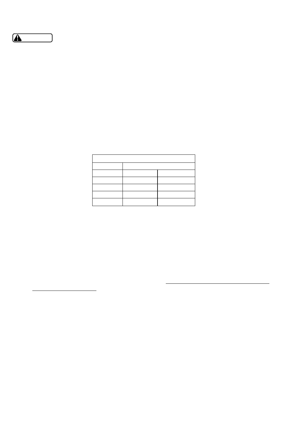
Maintain a minimum spacing around the drive as follows:
If it is necessary to drill or cut the drive enclosure or panel, extreme care must be taken to avoid damaging
drive components or contaminating the drive with metal fragments (which cause shorting of electrical
circuits). Cover drive components with a clean cloth to keep out metal chips and other debris. Use a
vacuum cleaner to clean drive components after drilling, even if chips do not appear to be present . Do not
attempt to use positive air pressure to blow chips out of drive, as this tends to lodge debris under electronic
components . Contaminating the drive with metal chips can cause drive failure and will void the warranty .
All drive models MUST be mounted in a vertical position for proper heatsink cooling. Fans or blowers
should be used to insure proper cooling in tight quarters. Do not mount drives above other drives or
heat producing equipment
that would impede the cooling of the drive . Note the ambient operating
temperature ratings for each drive model .
If it is necessary to drill or cut the drive enclosure or panel, extreme care must be taken to avoid damaging
drive components or contaminating the drive with metal fragments (which cause shorting of electrical
circuits). Cover drive components with a clean cloth to keep out metal chips and other debris. Use a
vacuum cleaner to clean drive components after drilling, even if chips do not appear to be present . Do
not attempt to use positive air pressure to blow chips out of drive, as this tends to lodge debris under
electronic components . Contaminating the drive with metal chips can cause drive failure and will void the
warranty . The MICRO Series is UL approved for solid state motor overload protection . Therefore, a
separate thermal overload relay is not required for single motor applications. In applications where one drive
is operating more than one motor, a separate thermal overload relay is required for each motor per NEC.
22
WARNING
SPACING REQUIREMENTS
SPACING
HP
INCHES
mm
0 .25 - 5
2
50
7 .5 - 25
4
100
30 - 60
6
150
75 - 150
8
200