KB Electronics KBAC-29 (1P) User Manual
Page 19
18
6.5
BOOST MODE SELECTION (J6) –
Jumper J6 is factory set to the “FIX”
position for Fixed Boost. For
Adjustable Boost using the BOOST
Trimpot, set Jumper J6 to the “ADJ”
position. See Figure 23. Also see
Section 12.8, on pages 24 – 25, for
the BOOST Trimpot range.
6.6
BRAKING MODE SELECTION (J7) –
Jumper J7 is factory set to the “RG”
position for Regenerative Braking when
the Start/Stop Switch is set to the
“STOP” position. For DC Injection
Braking, set Jumper J7 to the “INJ”
position. See Figure 24. Also see
Section 12.5, on page 23.
When the Injection Brake Mode is
selected, the DECEL Trimpot is used
to adjust the brake time and intensity.
6.7
RUN/FAULT OUTPUT RELAY
OPERATION SELECTION (J8) –
Jumper J8 is factory set to the “R”
position for “Run” operation of the
Run/Fault Relay. For “Fault” operation
of the Run/Fault Relay, set Jumper J8
to the “F” position. See Figure 25, on
page 19.
For Run/Fault Relay output contacts,
see Section 5.8, on pages 15 – 16.
The Run/Fault Relay contact status for
various drive operating conditions is
shown in Table 6, on page 16.
6.8
STOP CONTACT SELECTION (J9) –
Jumper J9 is factory set to the “NO”
position for a normally open stop
contact. For remote normally closed
stop contact, set Jumper J9 to the
“NC” position. See Figure 26, on
page 19. For wiring information, see
Section 5.5, on pages 14 – 15.
6.9
TORQUE MODE SELECTION (J10) –
Jumper J10 is factory set to the “CT”
position for Constant Torque Mode,
which is desirable for most machine
applications. For Variable Torque
Mode, used for HVAC and fan
applications, set Jumper J10 to the “VT” position. See Figure 27, on page 19.
6.10 I
2
t OVERLOAD SELECTION (J11) – Jumper J11 is factory set to the “1” position for Inverter Duty
Rated Motors. For Non Inverter Duty Rated Motors and HVAC applications, set Jumper J11 to the “2”
position. See Figure 28, on page 19. Also see Section 12.7, on page 24.
FIGURE 22
120 H
Z
& 100 H
Z
DRIVE OUTPUT FREQUENCY SELECTION
120 Hz Output with 60 Hz Motor
(J4 Installed in “2X” Position)
(J5 Installed in “60Hz” Position)
100 Hz Output with 50 Hz Motor
(J4 Installed in “2X” Position)
(J5 Installed in “50Hz” Position)
2X
J4
1X
50Hz
J5
60Hz
2X
J4
1X
50Hz
J5
60Hz
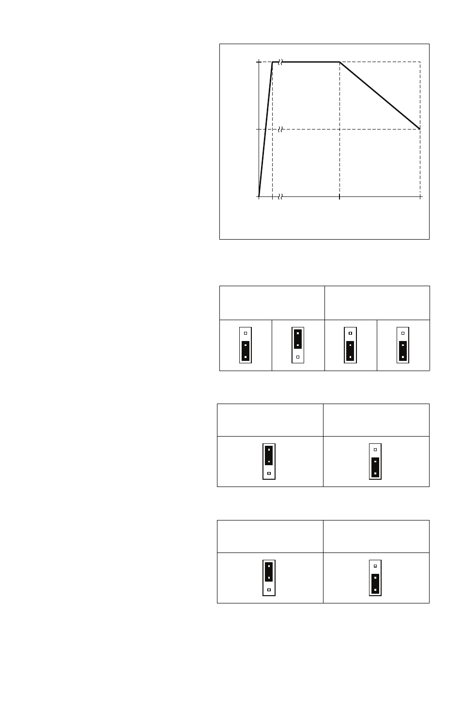
FIGURE 21 – AVAILABLE TORQUE
VS
. OUTPUT FREQUENCY
50/60
Output Frequency (Hz)
0
2
0
%
Torque
50
100/120
100
FIGURE 23 – FIXED OR ADJUSTABLE BOOST SELECTION
Fixed Boost
(Factory Setting)
(J6 Installed in “FIX” Position)
Adjustable Boost
(J6 Installed in “ADJ” Position)
ADJ
J6
FIX
ADJ
J6
FIX
FIGURE 24 – REGENERATIVE OR DC INJECTION BRAKING SELECTION
Regenerative Braking
(Factory Setting)
(J7 Installed in “RG” Position)
DC Injection Braking
(J7 Installed in “INJ” Position)
INJ
J7
RG
INJ
J7
RG