KB Electronics KBAC-29 (1P) User Manual
Page 10
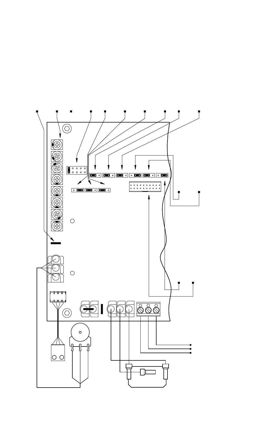
Output Contacts:
Run/Fault Relay
Start/Stop Switc
h:
Main Speed Potentiometer:
Diagnostic LEDs:
J4:
1X or up to 2X
J9:
Nor
mally Open or Closed
J11:
I
t Overload selection.
CON1:
Used to connect
optional accessories to the drive
.
Stop Contact selection.
Tor
que selection.
J10:
Constant or
Variable
J7:
Regener
ative or
Output Relay Oper
ation selection.
Injection Br
aking selection.
J8:
"Run" or "Fault"
J6:
Fixed or
Adjustable Boost selection.
Rated Motor RPM Oper
ation selection.
Motor Oper
ation selection.
J5:
60 Hz or 50 Hz
All jumpers and trimpots ar
e sho
wn in factor
y set positions.
J1:
AC Line Input
Voltage selection
J2:
Motor Horsepo
wer selection
3
.
(Models KBAC-24D
, 27D only).
J3:
Automatic Ride-Through
4
or Manual Start selection.
Used with optional Run-Stop-Jog Switc
h Kit.
Adjustable
Trimpots
2
.
JOG
Ter
minal.
See Section 6.6,
on pa
ge 18.
See Section 6.7,
on pa
ge 18.
See Section 6.4,
on pa
ge 17.
See Section 6.4,
on pa
ge 17.
See Section 6.5,
on pa
ge 18.
See Section 6.1,
on pa
ges 16 – 17.
See Section 6.2,
on pa
ge 17.
See Section 6.3,
on pa
ge 17.
See Section 12,
on pa
ges 22 – 25.
See
Table 2,
on pa
ge 8.
2
see Section 5.5,
see Section 5.9,
on pa
ge 16.
on pa
ges 14 – 15.
Normally Closed
Red
Normally Open
Relay Common
see Section 5.4,
on pa
ge 14.
Black
White
See Section 6.10,
on pa
ge 18.
See
Table 2,
on pa
ge 8.
See Section 6.8,
on pa
ge 18.
See Section 6.9,
on pa
ge 18.
White (Lo
w) (P1)
Violet (High) (P3)
Orange (Wiper) (P2)
see Section 11,
on pa
ges 21 – 22.
ST
ATUS
POWER
STOP
NC
NO
COM
FWD
COM
RUN
REV
COM
CON2
JOG
P1
P3
P2
ACCEL
MIN
MAX
JOG
CL
DECEL
BOOST
TB2
M
A
J3
2X
J4
50Hz
J5
60Hz
1X
J8
J9
NC
NO
F
J11
J10
CT
2
1
VT
CON1
FIX
J6
RG
R
INJ
J7
ADJ
A
J2
E
C
D
B
COMP
9
FIGURE
2
–
CONTROL
LA
YOUT
1
Notes:
1.
La
yout
of
Model
KBAC-24D
varies
slightl
y.
2.
On
Model
KBAC-24D,
the
JOG
and
COMP
Trimpots
are
loca
ted
verticall
y,
along
the
right
edge
of
the
PC
board
(below
the
mounting
screw).
3.
On
Model
KBAC-24D,
Jumper
J2
is
la
beled
“1”,
“3/4”,
“1/2”,
“1/4”,
“1/8”
(factor
y
set
to
the
“1”
position).
On
Model
KBAC-27D,
Jumper
J2
is
la
beled
“2”,
“1
1
⁄
2
”,
“1”,
“3/4”,
“1/2”
(factor
y
set
to
the
“1
1
⁄
2
”
position).
On
Models
KBAC-29,
45,
48,
Jumper
J2
is
la
beled
“A
”,
“B”,
“C”,
“D”,
“E”
(factor
y
set
according
to
Ta
ble
4,
on
pa
ge
10.
4.
On
Model
KBAC-24D,
Jumper
J3
is
la
beled
“A
UTO”
and
“MAN”.