American Dryer Corp. Phase 5 Microprocessor AD-170 User Manual
Page 31
27
7. Tighten cap screws progressively. There should remain a gap between the sheave hub and the flange of the
bushing.
IMPORTANT: Tighten screws evenly and progressively. Never allow the sheave to be drawn
in contact with the flange of the bushing. This gap should measure from 1/8"
to 1/4". Proper cap screw torque is 6 ft-lbs., if greater tightening forces are
applied, excess pressures will be created in the hub of the mounted sheave
which may cause it to crack.
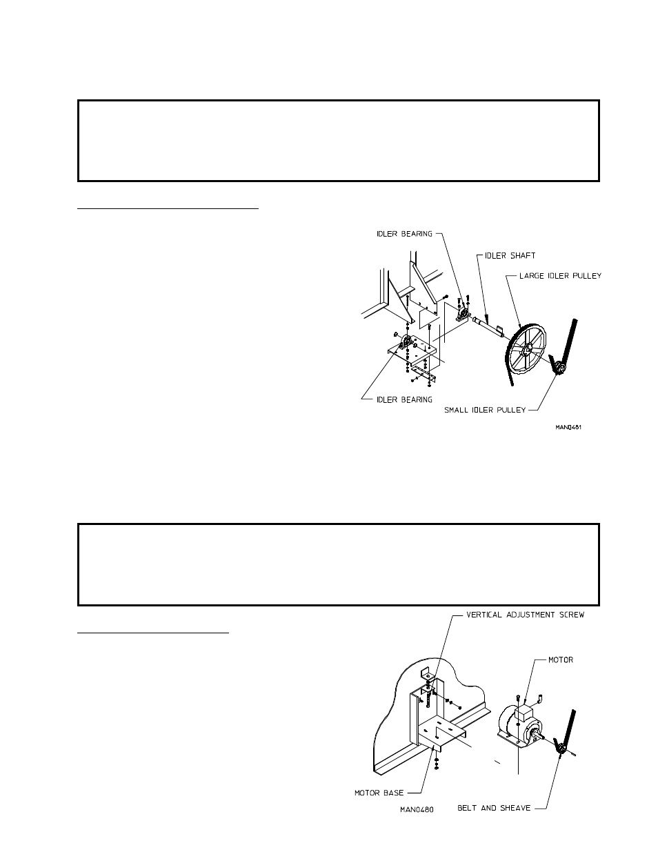
To Replace Large Idler Pulley
1. Loosen V-belts. Then, rotate pulley and roll V-belts
out of grooves.
2. Remove cap screws.
3. Insert cap screws in tapped removal holes and tighten
evenly until bushing becomes loose on shaft.
See Figure "A" on previous page.
4. Remove bushing, pulley, and key.
5. Assemble bushing and sheave as shown in figure "B"
on previous page. When cap screws are loosely
inserted, bushing remains fully expanded to provide
a sliding fit on the shaft.
6. Insert key on the shaft, then slide sheave to desired position with cap screw heads to the outside.
7. Tighten cap screws progressively. There should remain a gap between the sheave hub and the flange of the
bushing.
IMPORTANT: Tighten screws evenly and progressively. Never allow the sheave to be drawn
in contact with the flange of the bushing. This gap should measure from 1/8" to
1/4". Proper cap screw torque is 6 ft-lbs. If greater tightening forces are
applied, excess pressures will be created in the hub of the mounted sheave
which may cause it to crack.
To Replace Motor Pulley
1. Loosen V-belts. Rotate pulley and roll V-belts
out of grooves.
2. Remove cap screws from bushing.
3. Insert cap screws in tapped removal holes and
tighten evenly until bushing becomes loose on
shaft. See figure "A" on previous page.