D. gas burner assembly, E. drive motor, F. blower motor and impellor – American Dryer Corp. Phase 5 Microprocessor AD-170 User Manual
Page 13: For 60 hz gas models only), G. blower motor and impellor, For 50/60 hz steam models and 50 hz gas models)
9
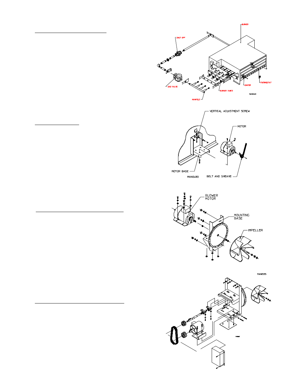
E. Drive Motor
The T.E.F.C. (totally enclosed, fan-cooled) drive motor
is located approximately lower center of the dryer. It sits
on an adjustable base so that the motor can be easily
adjusted to the left or right, up or down, forward or back-
ward. The drive motor is a 3/4 HP motor and operates
on 208 to 408 volts, 3Ø, 50/60 Hz.
F. Blower Motor and Impellor
(60 Hz Gas Models Only)
The blower motor is located on the back of the dryer at
the lower right-hand corner. The impellor is a backward
curved paddle wheel which is directly connected to the
shaft of the blower motor. The blower motor is a 3 HP
motor and operates on 208 to 460 volts, 3Ø, 50/60 Hz.
G. Blower Motor and Impellor
(50Hz, 60Hz Steam & 50Hz Gas)
The impellor on this design is shaft driven. The blower
motor drives the shaft on which the impellor is mounted.
This enables the impellor to run at a higher RPM, thereby
producing a higher air flow (CFM).
D. Gas Burner Assembly
Gas-heated dryers are equipped with a gas burner
assembly consisting of four (4) burner tubes, gas valve,
spark ignition probe assembly, sail switch, and hi-limit
thermostat. The inlet piping enters through the rear of
the dryer on the left-hand side (viewing from the front)
and runs to the front of the dryer where the gas valve is
located.