D. sail switch assembly, For gas models only), D. sail switch assembly (gas models only) – American Dryer Corp. Phase 5 Microprocessor AD-170 User Manual
Page 26
22
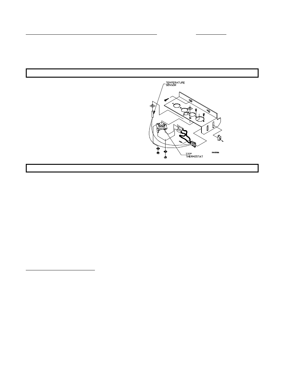
To Replace Lint Compartment Hi-Heat Protector (225 Degree) Thermostat
This thermostat is part of the "sensor bracket assembly" and is secured to the underside of the basket wrapper in
the lint compartment. As a safety device, this thermostat will open (shut off) the heating unit circuit if an
excessive temperature occurs. The dryer motors will remain on, even if the thermostat is open.
IMPORTANT: Under no circumstances should heat safety devices be disabled.
1. Discontinue power to dryer.
2. Remove lint drawer. Remove two (2)
screws securing lint door and remove
lint door.
3. Locate sensor bracket assembly and
loosen the two (2) Phillips head screws
securing bracket assembly to the
tumbler wrapper.
NOTE: DO NOT remove the screws.
4. Remove bracket assembly by slightly sliding bracket towards the rear of the dryer and to the left.
5. Disconnect sensor bracket harness connector and remove bracket assembly from dryer.
6. Disconnect the two (2) orange wires from the thermostat.
7. Disassemble thermostat from bracket assembly by removing the two (2) mounting screws, washers, and nuts.
8. Reverse this procedure for installing a hi-heat protector thermostat.
9. Reestablish power to the dryer.
D. Sail Switch Assembly (Gas Models Only)
The sail switch is a heat circuit safety device which controls the burner circuit only. When the dryer is operating
and there is proper airflow, the sail switch damper pulls in and closes the sail switch. Providing all the other
heat-related circuits are functioning properly, ignition should now be established. If an improper airflow occurs,
the sail switch damper will release, and the circuit will open.