American Dryer Corp. Phase 5 Microprocessor AD-170 User Manual
Page 19
15
4. Peel paper backing off new keyboard label assembly.
5. Holding the new keyboard label assembly close to
the panel, insert the keyboard ribbon through the
rectangular slot in the control panel. Align label
assembly into position by matching the red
viewing window on the label to the rectangular
cutout in the panel and gently press into place.
6. Connect keyboard ribbon to the computer.
7. Reestablish power to dryer.
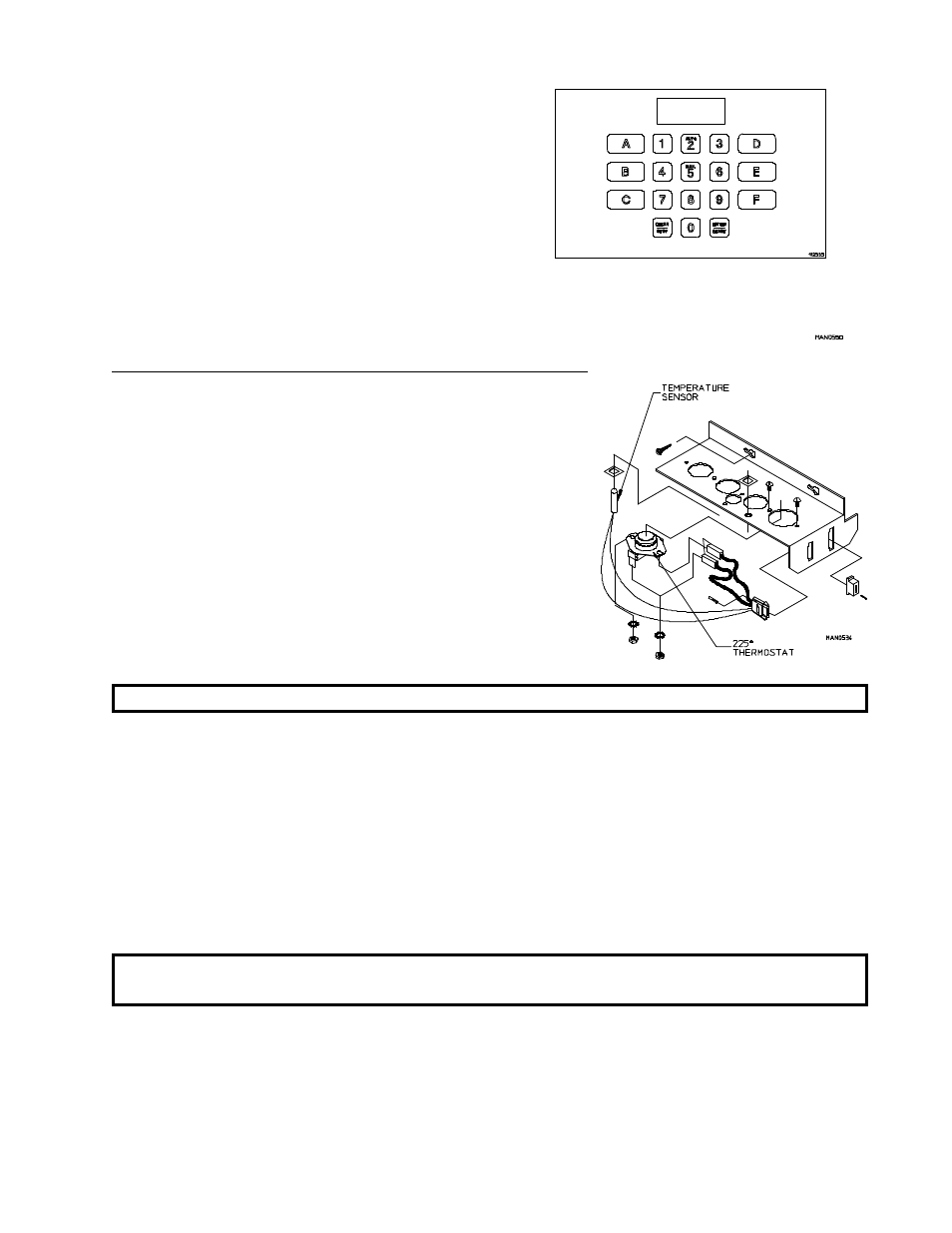
To Replace Microprocessor Temperature Sensor Probe
1. Discontinue power to dryer.
2. Remove lint drawer. Remove two (2) screws securing
lint door and remove lint door.
3. Remove microprocessor sensor bracket assembly from
dryer.
a. Disconnect sensor bracket harness connector.
b. Loosen the two (2) Phillips head screws
securing bracket assembly to dryer and remove
bracket from dryer.
NOTE: DO NOT remove screws.
4. Disassemble sensor probe from bracket assembly by removing the top push-on fastener securing the probe
from bracket. Use a small screwdriver to slowly pry the fastener off.
5. Disconnect the two (2) orange wires from the high heat (225 degree) thermostat, and remove modular bracket
connector, wires, and probe from bracket assembly.
6. Install new sensor probe assembly (ADC P/N 880251) by reversing procedure.
7. Reestablish power to the dryer.
NOTE: If, when power is reestablished, the computer display reads "dSFL", check for a loose
connection in the wiring.