Reattach heat sink – Sonnet Technologies Encore_ST G4 (With No Heatsink) Processor Upgrade Card User Manual
Page 5
5
Figure 15
Figure 14
Figure 13
Figure 12
screw hole
screw hole
screw hole
Encore/ST card
Encore/ST card
screw
screw
screw
short
section
long
section
fins
heat sink
clip
dimple
clip
heat sink
post
post
clip
clip
Installation—AGP Graphics and Gigabit Ethernet Models
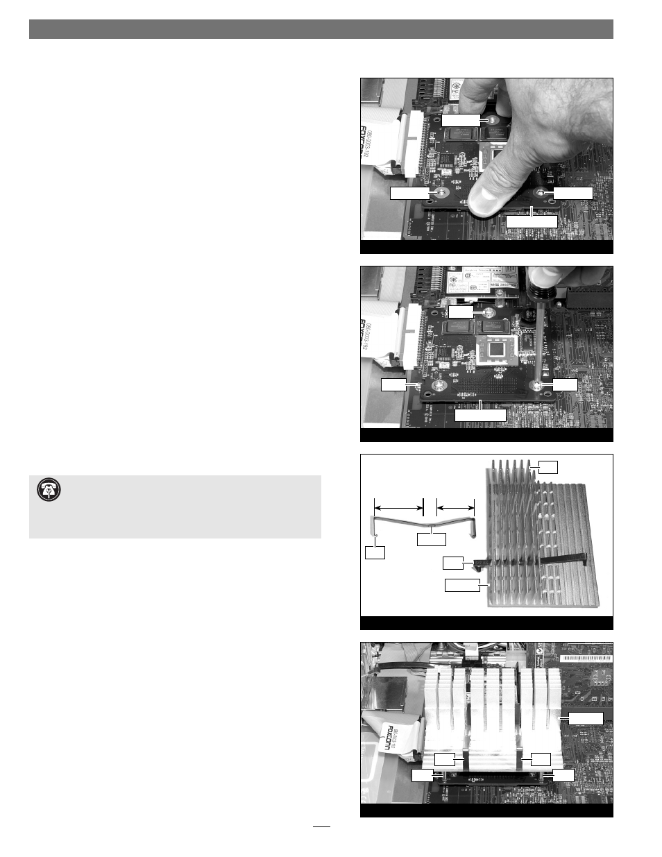
4. Align the Encore/ST card’s three screw holes with the three
threaded posts on the logic board, then set the card gently on
top of the posts (Figure 12). Make sure the connectors are lined
up, then, grasping the card by its edges, gently press it straight
down until the connectors snap together. Verify the connectors
are completely coupled by gently pulling up on the edges of the
Encore/ST board; the board should remain fi rmly in place.
5. Snugly secure the Encore/ST card to the logic board with the
three screws you removed previously; do not overtighten the
screws (Figure 13).
Reattach Heat Sink
1. The heat sink clips must be positioned properly on the heat
sink. Examine the clips and note the short and long sections, and
the dimple. When you reattach the heat sink, each clip will be
placed on the heat sink so its long section rests in the tall fi n area
(Figure 14). Please note, this may be opposite of how the clips
were originally installed.
2. Set the clips aside. With the heat sink’s tall fi ns at the back,
guide the heat sink’s posts into the holes on the Encore/ST card;
place the clips across the heat sink, with the long sections resting
in the tall fi n area; make sure the clips do not get caught between
the card and the heat sink (Figure 15). Verify that the heat sink
is resting fl at and level across the top of the Encore/ST card.
Support Note:
The following steps address the installation of
your system’s heat sink. Please note, only the single processor
heat sink is pictured, but the procedure is identical for the dual pro-
cessor heat sink. Please also note, that your heat sink may differ from
what is pictured.