Reattach heat sink, Reinstall fan assembly and close computer – Sonnet Technologies Encore_ST G4 (With No Heatsink) Processor Upgrade Card User Manual
Page 15
15
Figure 53
Figure 52
Figure 51
Figure 50
2-pin
connector
modem
filter
fan assembly
tab
Encore/ST
card
clip
clip
heat sink
clip
heat sink
clip
groove
heat sink
Installation—QuickSilver 2001 and 2002 Models
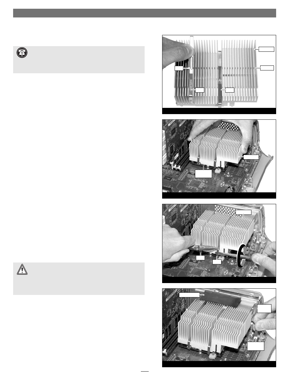
Reattach Heat Sink
1. Make sure the heat sink clips are positioned properly on the
heat sink (Figure 50); your heat sink may differ from what is
pictured. Examine each clip and note the tab on the edge. Place
each clip so its tab fi ts into the groove on the heat sink, and the
clip drops to the bottom of the heat sink’s fi ns.
2. Guide the heat sink’s mounting posts into the holes on the
Encore/ST card; make sure the clips do not get caught between
the card and the heat sink (Figure 51). Verify that the heat sink is
resting fl at and level across the top of the Encore card.
3. Lift up a clip and hook it over the back edge of the Encore card,
then pull it toward you. Repeat this process with the other clip.
Carefully insert a fl at blade screwdriver between the left clip and
the edge of the heat sink; do not touch the edge of the proces-
sor card. Using extreme caution, press down on the edge of the
clip with needle-nose pliers, and twist the screwdriver to hook
the clip over the edge of the Encore/ST card. Be certain that the
clip is grasping the card at both ends. Repeat this process with
the other clip (Figure 52).
4. Visually inspect all four points where the clips attach to the
Encore/ST card. It is easy for the clips to be attached only to the
heat sink, which can lead to destructive overheating of your
upgrade card. Verify that each clip is grasping the card at each
end.
Reinstall Fan Assembly and Close Computer
1. While holding its 2-pin connector, place the fan assembly
between the heat sink and the back panel of the computer,
against the modem fi lter (Figure 53). Carefully plug in the fan’s
2-pin connector to the connector on the logic board (Figure 53).
WARNING:
The heat sink must be secured firmly, flatly and
completely for reliable and stable operation. If the clips are
not properly attached to the Encore card at all four contact points,
proper cooling of the processor will not occur and the processor will
overheat, causing severe damage to the Encore card. Repairs due to
this damage are not covered by warranty.
Support Note: The following steps address the installation of
your system’s heat sink. Please note, only the single processor
heat sink is pictured, but the procedure is similar for the dual proces-
sor heat sink. Please also note, that your heat sink may differ from
what is pictured.