Ronan X11CA Hardware Manual User Manual
Page 20
Rev 1.0 Series X11CA Hardware Manual
2. X11CA Hardware Setup
Hardware Control-© 2002 Ronan Engineering
16
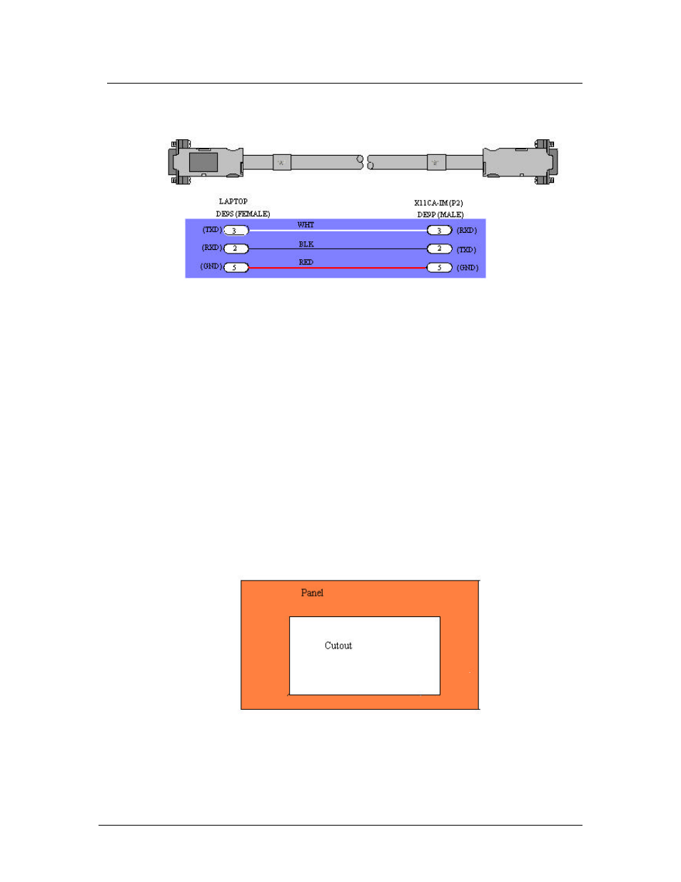
Figure 2-11 RS232 Cable from Host PC to X11CA-IM Connection
2.5 Mounting
Refer the mounting diagrams on the enclosed CD ROM, X11CA Drawings and
Sequence Chart, for detail.
2.5.1 Mounting the Modules in the Alarm Cabinet
The annunciator is shipped with all of the alarm/lamp modules, auxiliary
contact module(s) and flasher module(s) installed in the cabinet, as specified
by purchase order.
External horn relay(s), reflash relay, common alarm relay, relay sockets are
packed separately.
2.5.2 Mounting the Alarm Cabinet to the Panel
1. Position the X11CA alarm cabinet into the cutout hole on the panel.
Figure 2-12 Cutout area of the panel