Ronan X11CA Hardware Manual User Manual
Page 17
Rev 1.0 Series X11CA Hardware Manual
2. X11CA Hardware Setup
Hardware Control-© 2002 Ronan Engineering
13
2.2.5 RS485 Network
The X11CA Annunciator uses a typical RS-485 four-wire multidrop
configuration system. All slave modules communicate with the master module,
X11CA IM only, and the address of each slave module is selectable by the
jumper, J9, using the binary code.
Jumper 9
Each X11CA module board must have a unique binary address to
communicate with the X11CA Configuration program and the X11CA-
IM. This address is determined by setting the jumper, J9.
Refer to the conversion table on page 40 to convert from 00000001
2
to
1111 1111
10.
Jumper 9 of Appendix B: Data Conversion (Bin to Dec)
Table shows the switch setting for 00000001
2.
The RS485 driver, U10, is used as a RS485 to TTL converter.
2.2.6 Input Response Time
The default response time of each point is 20 milliseconds, but it can be
modified using the X11CA operating software.
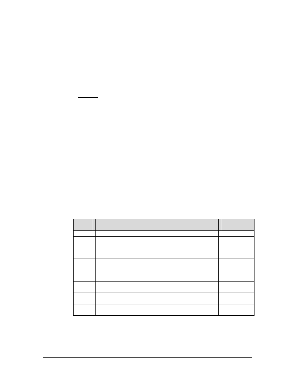
2.2.7 Summary of Jumper Settings
Jumper
NO.
Description
Default
Settings
J1
Connector to the Terminal board (Module No. X11C451)
J2
RS485 terminator. If both top and bottom pins are
connected, RS485 termination will be enabled.
No connection
except the first
alarm module
J3
Not Available
J4
Connector to the front panel of the Lamp board (Module No.
X11-1038)
J5
Connector to the Communication module (Module No. X11-
1033)
J6
Polarity of field input contact B. Either Normally Open or
Normally Closed.
NO or NC.
J7
Polarity of field input contact C. Either Normally Open or
Normally Closed.
NO or NC.
J8
Polarity of field input contact D. Either Normally Open or
Normally Closed.
NO or NC.