Robertshaw DSL-520P User Manual
Page 7
limiting devices which provide protection against excessive current draws caused by circum-
stances such as wiring shorts on an output. These devices, referred to as polyfuses, are acti-
vated in general when the current draw exceeds 2.5 Amps. The value and the duration of the
excess current is taken into account. The polyfuses will allow excess currents of very short
duration (i.e., spikes) in order to prevent circuit interruptions by noisy lines or occasional minor
surges. In its current limiting mode, the polyfuses reduce the output current to milliamps.
NOTE:
The low leakage current may be sufficient to produce a small voltage reading when measured
with a volt meter with a high input impedance.
When the cause of the excess current has been removed and the current draw is returned to a
value below 2.5Amps, the polyfuses will reestablish full output current; in some instances this
may take up to twenty (20) seconds. Polyfuses eliminate the need to replace blown fuses.
The SZP control module uses red LEDs to indicate when a problem exists with the current
being drawn from certain circuits. An LED exists for the following on-board circuits:
* each zone damper circuit
* each zone thermostat circuit (current limited at 0.1Amp)
* on the cool terminal strip
* on the heat terminal strip
15
4
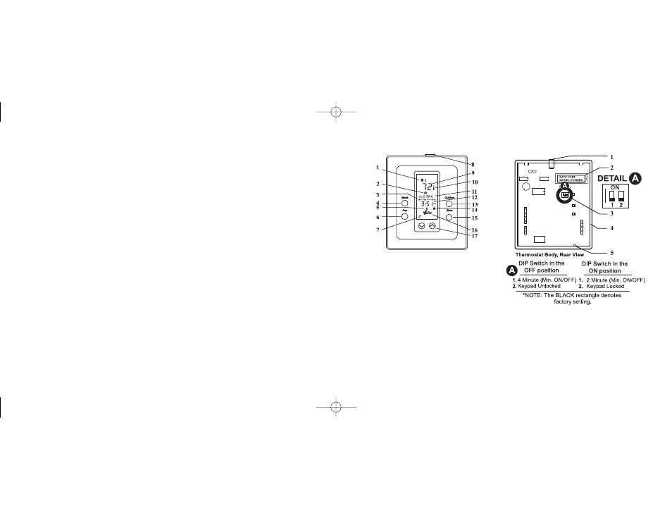
1. Perimeter Heat LED
2. Date Code & Model Number
3. DIP Switch
4. Printed circuit board
5. Thermistor: measures room temperature
1. Outdoor Remote Sensor
2. Heating (Flame %), Cooling (Snowflake ☛)
3. Days of the week
4. MODE button (Toggles between Heat, Cool, Auto, Off)
5. Temporary Override
6. FAN button (Toggles between Constant or Automatic
Fan)
7. Communication Link established
8. Perimeter Heat LED
9. Room Temperature Display
10. Temperature Setpoint change
11. Events (Morning ✣, Day ✥, Evening ✤, Night ✠)
12. Time of day or Mode of Operation
13. OUTDOOR button (Displays outdoor temperature)
14. Keypad locked
15. ZONE button (Displays zone number of thermostat)
16. Fan
17. ✟ ✞ buttons (Raise or lower setpoint or toggle
between ˚C or ˚F when pressed simultaneously)
DSL-520P USER INTERFACE, LED AND SWITCHES
110-906 9/25/00 10:47 AM Page 7