Robertshaw DSL-520P User Manual
Page 16
4. Return the temperature setpoint to its original value. Note that selecting the OFF mode
clears the ✧ symbol, ending the temporary override.
5. Press the FAN button until the fan symbol (
'
) appears; the green LED (fan) will light
up at the SZP control module.
6. Press the FAN button again if constant fan is not required.
DAMPERS
Robertshaw dampers are designed to work with low pressure systems (1.0" WC or less).
Balancing dampers should be installed ahead of all zone dampers. Zone dampers should be
installed 10 ft. (3 m) back from discharge grille. A flex or lined duct is recommended for the
last 5 ft. (1.5 m). Enerstat dampers are two (2) position dampers. Two (2) wire dampers are
powered closed and spring return open. Three (3) wire dampers are powered closed and pow-
ered open. For applications requiring minimum air ventilation, an adjustment screw is avail-
able to set the damper to a specified minimum open position. Enerstat dampers are shipped
from the factory with the minimum position adjustment screw in the fully closed position;
allow for a 3% to 5% leakage with damper closed. The control module has five (5) terminals
at each zone terminal strip for damper connections, which are as follows:
13
and RS+V). There are no switches to set. The thermostat detects the remote sensor connection
and controls temperature based on the data received.
PERIMETER HEAT
The W1 and R terminals on the DSL-520P are designated for use with perimeter heat, one for
each zone. The perimeter heat will be activated when the thermostat requests heat and the SZP
control module is not demanding heat from the main heating source.
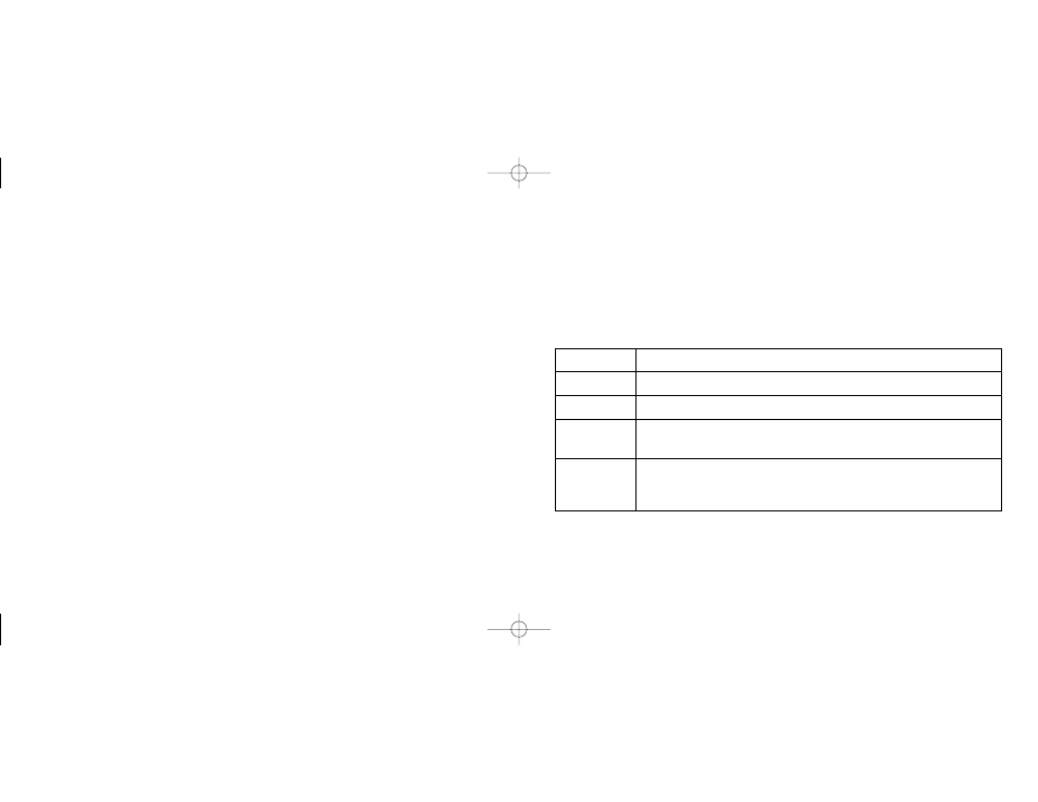
Terminal
Function
R
24VAC input for perimeter heat
W1
Perimeter heat dry contact output
RS2, RS1
Indoor remote sensor connections. Refer to the instructions
RS+V
included with the sensor.
1-4
Communication terminals to the SZP control module. The termi-
nals must be connected 1-1, 2-2, 3-3, 4-4 to function and prevent
damage.
DSL-520P OUTPUT TERMINALS, LED DESIGNATIONS
6
110-906 9/25/00 10:47 AM Page 9