Rma-303 indirect charge - maintenance – Ransburg RMA Indirect A12869 User Manual
Page 71
RMA-303 Indirect Charge - Maintenance
LN-9268-11.4
66
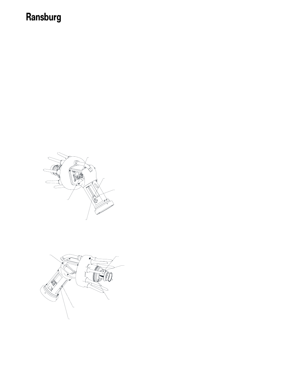
EXTERNAL CUP WASH LINE CONNECTED
TO ONE OUTLET OF "Y" FITTING
INTERNAL CUP WASH LINE CONNECTED
TO REAR OF ATOMIZER BODY
A11351-03
INTERNAL CUP WASH LINE CONNECTED
TO ONE OUTLET IF "Y" FITTING
A11351-04
CUP WASH LINE
THIS TUBE PASSES THROUGH THE
ATOMIZER BODY FROM TO FRONT
TO THE BACK OF THE ATOMIZER
A11894-00
SOLVENT "Y" FITTING
Figure 33: Interior/ Exterior Cup Wash
Tube Locations
Figure 34: Exterior Cup Wash Tube Route
EXTERNAL CUP WASH TUBE
A11350-04
A11276-00 FITTING
A11305-00 FERRULE
A11276-00 FITTING
A11305-00 FERRULE
EXTERNAL CUP WASH TUBING
THROUGH ATOMIZER BODY
EXTERNAL CUP WASH CONNECTED TO
ONE OUTLET OF "Y" FITTING
A11894-00
SOLVENT "Y" FITTING
Exterior Solvent Wash Line Removal/
Replacement
Occasionally the exterior solvent wash line
assembly (A11351-04) will have to be re-
moved and replaced due to kinks or fitting fer-
rule leakage.
To remove, loosen fitting from valve manifold
assembly (A11692-00) using a 3/16" end
wrench. Cut the tubing above the fitting. Fit-
ting may be reused, but the ferrule must be
replaced.
Loosen the fitting at the shaping air inner ring
and the atomizer body. Pull the entire tube
through the atomizer body. Again, fittings can
be reused, but ferrule must be replaced.
To reinstall, insert open end of A11351-04 as-
sembly into front of atomizer body and push all
the way through. Install ferrule and fitting over
tube and install at valve manifold end first!
Tighten fitting to a stop, then 1/4 more turn.
Next, pull some of the slack out of the line be-
fore tightening the next fitting and ferrule into
the atomizer body. Tighten to stop and then
1/4 turn more. Next, tighten the remaining end
of the tube into the inner shaping air ring.
Tighten to stop and tighten 1/4 turn more.
Cup Wash Manifold Removal/ Replacement
(Applicator Off Robot)
(See Figures 35 and 36)
Removal
Remove the mounting ring by first removing
the break-away ring. Loosen the six (6) 1/4-20
screws (using a flat blade screwdriver) that
holds the break-away ring to the rear plate as-
sembly. The break-away ring and the mount-
ing ring will now come off.
Loosen the fiber optic assembly in the rear
plate by loosening the set screw with a 3/32"
hex key. Pull the fiber optic cable from its hole
in the solvent manifold and rear plate assem-
bly. Leave end loose in the atomizer exten-
sion.
Using the tubing removal tool (A11373-00),
select the appropriate size end for the tube to
be removed, 8mm or 6mm. The 8mm end will
also fit over the 10mm green turbine air tube.
Place the opening around the tube and press
down on the quick release cullet. Using your
other hand, pull the tubing from the cullet. Re-
move all tubing from the collets. Also, remove
the fluid tubes held on with compression nuts.
On the cup wash manifold end, remove the
cup wash line from the manifold by unscrewing
the