Kasco Marine VFX Series User Manual
Page 7
7
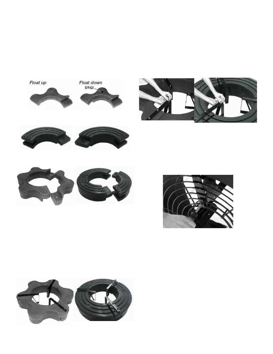
4. Turn the assembly upside down and place the Bot-
tom Float Brackets (Part #B3) over the bolts, the ends
of which should now be extending through the assem-
bly. Loosely install the six 3/8” Lock Nuts (Part #B5)
on the ends of the bolts (do not tighten yet). Connect
the Top and Bottom Float Brackets using three 1/4” x
3/4” Bolts (Part #B7) with three 1/4” Lock Washers
(Part #B8) and three 1/4” Nuts (Part #B12) and tighten
using the 7/16” wrench and socket.
8400, 2.3
5.1, 5.3
5. Stand the assembly on its side and center the Top
Screen (Part #B10) inside the three Top Float Brack-
ets. Attach the screen by spanning each Top Screen
Clip (Part #B11) across the two innermost rings on the
screen and the hole in the float bracket. Insert the 3/4”
Brass Screws (Part #B14) and attach with 1/4” Lock
Washers and 1/4” Nuts to secure the screen to the float
assembly.
6. Return the assembly to the upside down position
and place the motor assembly (Stainless Steel can side
up, black tube down) in the center of the float. Align
the 3 taller legs of the black aerator tube with the 3
float brackets. Attach the motor to the float using the
1/4” x 1” bolts (Part #B6). Attach to the float bracket
using the two middle holes of the float bracket. Tight-
en using the 1/4” x 1” Bolts with 1/4” Lock Washers
using the 7/16” socket and wrench. The 1” bolts will
screw directly into the legs of the black aerator tube.
ual. Make sure you have all the parts needed. If any
shortages are found, contact your Kasco representative
immediately.
2. Arrange the three Float Sections (Part #B1) upright
(plug on bottom) so the overlap of one section aligns
with the next section and loosely push the three sec-
tions together to form a continuous ring.
8400, 2.3
5.1, 5.3
Float Up (plug)
Float Down
8400, 2.3
5.1, 5.3
3. Position one Top Float Bracket (Part #B2) so that
the bolt holes in the bracket align with the bolt holes
in the two adjoined float sections and insert two 9”
Coated Bolts (Part #B4) through the assembly. This
may require some minor repositioning of the float sec-
tions as you push the bolt all the way through. Do not
force the bolt through. Repeat for the remaining two
joints.
8400, 2.3
5.1, 5.3