Kasco Marine VFX Series User Manual
Page 4
4
Also Included:
• Mesh screen(1) and cable ties(10)
• Cord in separate box (1) (depending on size of
cord)
• Control Box (C-25 for 120V units in Float box
or C-85 for 240V units in separate box) (1) (Not
Pictured)
TOOLS & SUPPLIES NEEDED
• Anchors or stakes for installing unit (2)
• # 2 Phillips head screw driver
• 120V or 240V Electrical Supply near pond on a
post with room for mounting the C-25 or C-85
• Two 12” pieces of 1” galvanized pipe for weight-
ing ropes (optional)
• #10 x 1” long or longer screw(s) for mounting the
C-25 (3) or C-85 (4)
• 9/16” Socket and Ratchet
• 9/16” Wrench
• 11/32” wrench (for #8 fasteners)
2400VFX, 3400(H)VFX, 4400(H)VFX
Assembly
1.
Make sure you have all the parts needed. If any
shortages are found, contact your Kasco representative
immediately.
2. Set motor housing upright (stainless steel can down) on
a flat surface.
3. Peel off the adhesive on one of the Cushions for the
aerator housing legs (Part 8). Stick to the top of the aerator
housing leg and repeat for the other three cushions. Rest
the float on the 4 legs of the housing making sure logo on
float is up.
cushion
logo
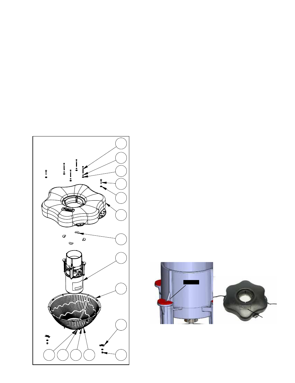
4. Ensure correct alignment by twisting the float gently
around the motor housing until the power cord guide lines
up with the cord. See diagram below of bottom side of
float. The 4 bolt holes in the float should line up with bolt
receptacles on unit.
2400VFX, 3400(H)VFX, 4400(H)VFX Parts
Included
1. Aerator (Unit w/cord or unit with Disconnect (1)
2. Float (with two 50’ mooring ropes attached) (1)
3. 1/4-20 x 3 1/2” Phillips Pan Head Screw (4)
4. 1/4” split washers (4)
5. 1/4” (3/4” outer diameter) Flat Washer (4)
6. 3/8”-16 x 1-3/4” Hex Head Bolt (2)
7. 3/8” Flat Washer (4)
8. Cushions for Legs (4)
9. Bottom Screen Section (3)
10. Bottom Screen Clips (2)
11. 3/8”-16 Nylon Lock Nut (2)
12. #8 nut (6)
13. #8 flat washer (12)
14. #8 lock washer (6)
15. #8 x 1/2” Screw (6)
1
2
3
4
5
6
7
8
9
12
10
11
13
14
15
REV.
ECO#
DESCRIPTION
DR'N BY
DATE
DES ENG CH'K BY
1
INITIAL RELEASE
XXXX-XXXX-XX
DO NOT SCALE DRAWING
C.A.D. GENERATED DRAWING
800 DEERE ROAD
PRESCOTT, WI 54021-1241
X
FX FLOAT ASSEMBLY W/SCREEN
X
X
X
X
THIS DRAWING CONTAINS PROPRIETARY
INFORMATION AND SHALL NOT BE USED,
REPRODUCED OR DISTRIBUTED WITHOUT
THE PRIOR WRITTEN CONSENT OF
KASCO MARINE, INCORPORATED
.X .02 [.508] .XX .010 [.254]
.XXX .005 [.127] ANGULAR 0.5
UNLESS OTHERWISE SPECIFIED
DIMENSIONS ARE IN INCHES.
DIMENSIONS IN [ ] ARE MILLIMETERS.
TOLERANCES ON:
THIS DOCUMENT HAS BEEN ISSUED
FOR ENGINEERING INFORMATIONAL
PURPOSES ONLY. ANY REVISIONS
TO THE CONTENT OF THIS DOCUMENT
MUST BE INCORPORATED INTO THE
ORIGINAL CAD FILE.
THIRD ANGLE PROJECTION
TITLE:
XXXX-XXXX-XX
SHEET 1 OF 1
FINISH:
MATERIAL:
SCALE: 1:24
DWG. NO.