General Tools and Instruments 840 Pro Doweling Kit User Manual
Page 9
9. Loosen SLIDE LOCK SCREW (E)
and, starting from the marked
line on board “B”, move the
SLIDE (F) along the SCALE ROD
(G) until the distance the SLIDE
(F) is away from the line is half
the thickness of board “A”. Use
the graduations marked on the
SCALE ROD (G) for measuring (See Figure 11).
Once aligned, tighten SLIDE LOCK SCREW (E).
10. Lift TURRET (H) and turn until the correct size hole is
aligned with the INDEX MARK (D). The TURRET (H) will snap
into place when properly located.
11. ENSURE THE DRILL IS TURNED OFF. Place a depth stop
collar on the drill bit at the proper depth to drill the first hole.
NOTE: Position the collar to allow for TURRET (H) height as
well as desired depth of hole.
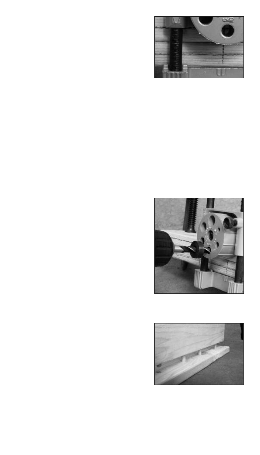
12. Ensure SLIDE (F) is locked at
proper position and drill dowel
hole in board “B”. The hole in the
TURRET (H) will help you keep
the drill straight (See Figure 12).
13. With clamp in place, loosen the
jig CLAMP SCREW (B) and move
the jig so the next marked
location on the board aligns with
the INDEX MARK (D) on the jig.
14. Gently tighten the CLAMP SCREW
(B) and repeat steps 8-13 until all
dowel holes are drilled.
15. Apply glue to the dowel pins and
insert them in the holes in board
“A” . Align the holes in board “B”
with dowel pins connect boards
“A” and “B” to make the joint
(See Figure 13).
Figure 11
Figure 12
Figure 13
9