Finish Thompson UC User Manual
Page 16
16
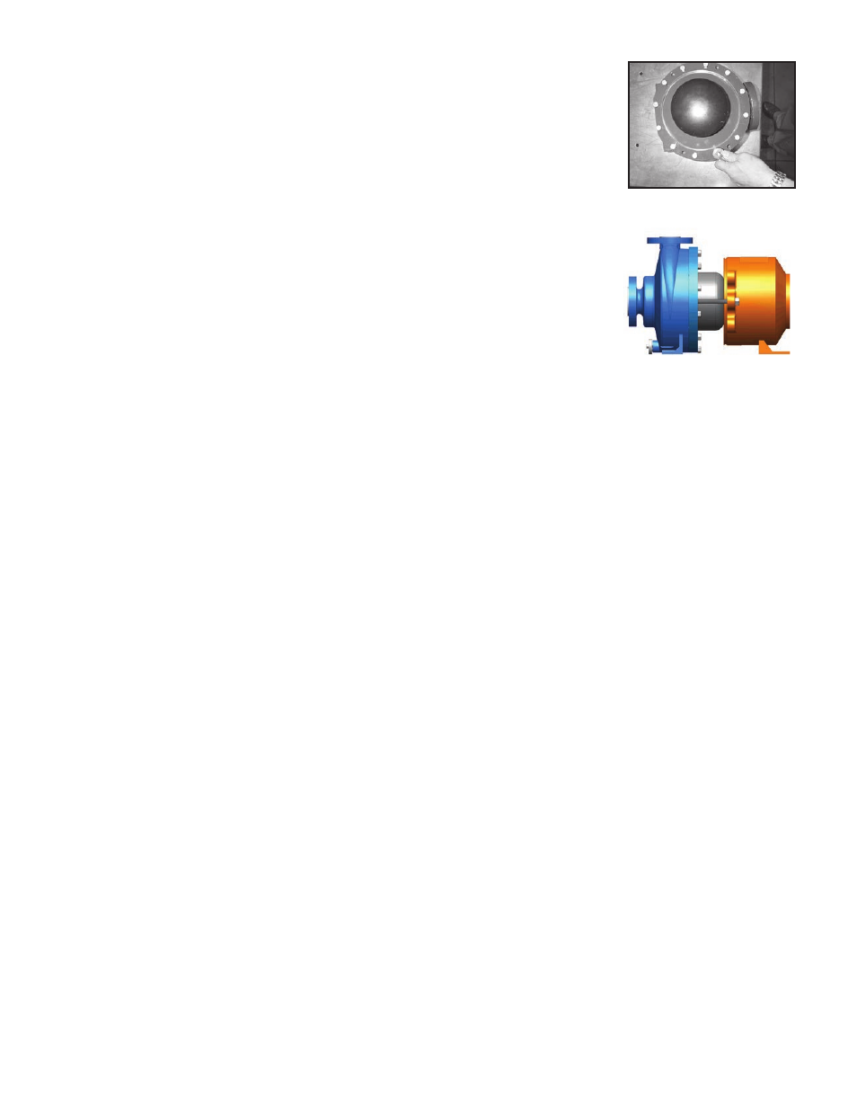
figure 37
6. Place the rounded edge of the clamp ring (Item 7) over the barrier assembly and position on
the rear face of the casing. Make sure to align the flat on the bottom of the clamp ring
with the flat on the bottom of the casing. Attach the clamp ring with (12) 3/8” socket head
cap screws (item 13). Tighten evenly around circumference. Torque the screws to 35 ft-lbs
(47 N-m) unlubricated. See figure 37.
7. Using a 3/4” socket, turn the (3) jackscrews (item 14) clockwise until the heads touch the
motor adapter (item 9).
8. Carefully slide the wet end towards the motor adapter until it touches the jackscrews (there
will be some magnetic attraction). See figure 38.
9. Slowly and evenly turn the jackscrews counterclockwise to allow the wet end to slowly slide
into the motor adapter. When the jackscrews are fully retracted, lift the wet end slightly and
slide it onto the motor adapter’s locating flange.
10. Bolt the wet end to the motor adapter by re-installing the (4) 1/2” hex head cap screws (item
15) and torque evenly to 75 ft-lbs (102 N-m).
figure 38