Finish Thompson UC User Manual
Page 12
12
8. Remove the impeller assembly and the shaft from the casing. See figure 13.
CAUTION: The shaft and impeller can be damaged if dropped.
figure 13
Disassembly
Power End (motor side)
WARNING: This pump should only be disassembled and assembled using the recommended
procedures. The magnetic attraction is powerful enough to rapidly pull the motor end and the
wet end together. ALWAYS use the jackscrews (item 14) to assemble/disassemble the pump.
Do not place fingers between the mating surfaces of the motor and wet ends to avoid injuries.
Keep the drive magnet and impeller assembly away from metal chips or particles.
1. Remove the two M8 hex nuts and lock washers (Items 21 & 22) & M8 hex head bolts and lock
washers (Items 22 & 23). Pull the magnet drive hub (Item 8A) away from the shaft adapter
(Item 8B). If the magnet drive hub is difficult to remove, you can thread (2) M8 hex head bolts
(item 23) into the extra set of holes to use as jackscrews to pry it off. Make sure to apply
equal turns to the bolts to pull the magnet drive hub off evenly. See figure 14.
2. Remove the four motor adapter bolts and lock washers (items 16 & 16A). Pull the motor
adapter (Item 9) off the motor. For IEC 160 frame, remove the motor adapter from the
motor adapter flange (Item 10). See figure 15.
3. Remove the two set screws (Item 27) for NEMA frames or shaft bolt for IEC frames. See
figure 16.
4. If replacing the motor for an IEC 160 frame, remove the four motor adapter flange bolts
to remove the motor adapter flange.
figure 14
figure 15
figure 16
Examination
The first scheduled inspection should take place after the first three months or approximately after
2000 hours of run time. This is to insure that there is no damage from any solids or particulate,
cavitation or run dry. Reinspect after six to twelve months depending on the results of the initial
inspection.
Note: All pumps should be checked for leaks on a regular basis. If any leaks are detected, the
pump should be repaired immediately.
Note: A new o-ring (item 12) will be required after pump inspection. If the drain flange is removed,
replace the gasket (item 11A)
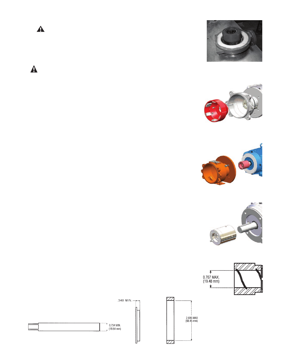
1. Inspect the bushings (items 4A, 4B) - The silicon carbide parts will not wear under normal
operation. Polishing on a silicon carbide surface is a normal occurrence and usually does not
require replacement. Check for signs of melting around the perimeter of the bushings. Make
sure that the spiral groove on the bushing ID is not plugged. Check for chips or cracks on the
rear face. Check bushings for wear (see figure 17). If the bushings appear worn, follow the
steps listed in the section “Replacing Wear Components, Impeller Bushings.”
2. Check for cracks or excessive wear on the shaft (item 5), impeller thrust ring (item 3A) and
rear sealing ring (item 4C). Replace if cracked or excessively worn. See figure 18.
figure 17
figure 18