Replacing wear components – Finish Thompson UC User Manual
Page 13
13
Shaft Support/Front Thrust Washer Removal
1. Remove the casing (item 1) from the base plate and piping.
2. Place the casing in an arbor press with ETFE lining side down.
3. Place arbor on the nose of the front shaft support (item 2) and carefully
press the front shaft support out of casing. See figure 19.
3. Check for signs of deformation or melting in the shaft support (item 2) and the barrier liner where the pump shaft is positioned.
Dry running the pump during its initial start-up or operation can cause heat-related damage to these components.
4. Inspect the casing liner. It is important that there are no abrasions or cuts deeper than .04 inch in the lining. These cracks may
occur if the lining is corroded or abraded. Liner damage can usually be detected visually. Some hairline cracks require an
electrostatic discharge tester to detect.
5. Locate the impeller vanes (impeller is item 3). Make certain that there are no obstructions. If there is an obstruction in any of the
flow paths, then an imbalance may cause excessive wear on the pump shaft and impeller bushings.
6. Check the impeller drive assembly (item 4) for cracks or grooves larger than .02 inch. If a fluid comes in direct contact with the
magnets, the magnets may swell, cause rubbing, and damage the barrier assembly (item 6).
7. Inspect the barrier assembly for signs of abrasion. Replace the barrier assembly if there are grooves or scratches that are
deeper than .04 inch.
Replacing Wear Components
Use the following procedures to replace any wear components that are excessively worn, cracked or broken.
figure 19
Installation of Replacement Support/Front Thrust Washer
1. Place the casing in an arbor press with the suction flange down.
2. Put front thrust washer into new shaft support.
3. Position the front shaft support in the bore of the casing suction and align the anti-rotation pins on the front shaft support with
the blind holes in the casing.
4. Press evenly on the face of the plastic shaft support with a soft-faced arbor until the front shaft support is fully seated in the
bore.
Impeller Thrust Ring
The impeller thrust ring is located in the front of the impeller shroud.
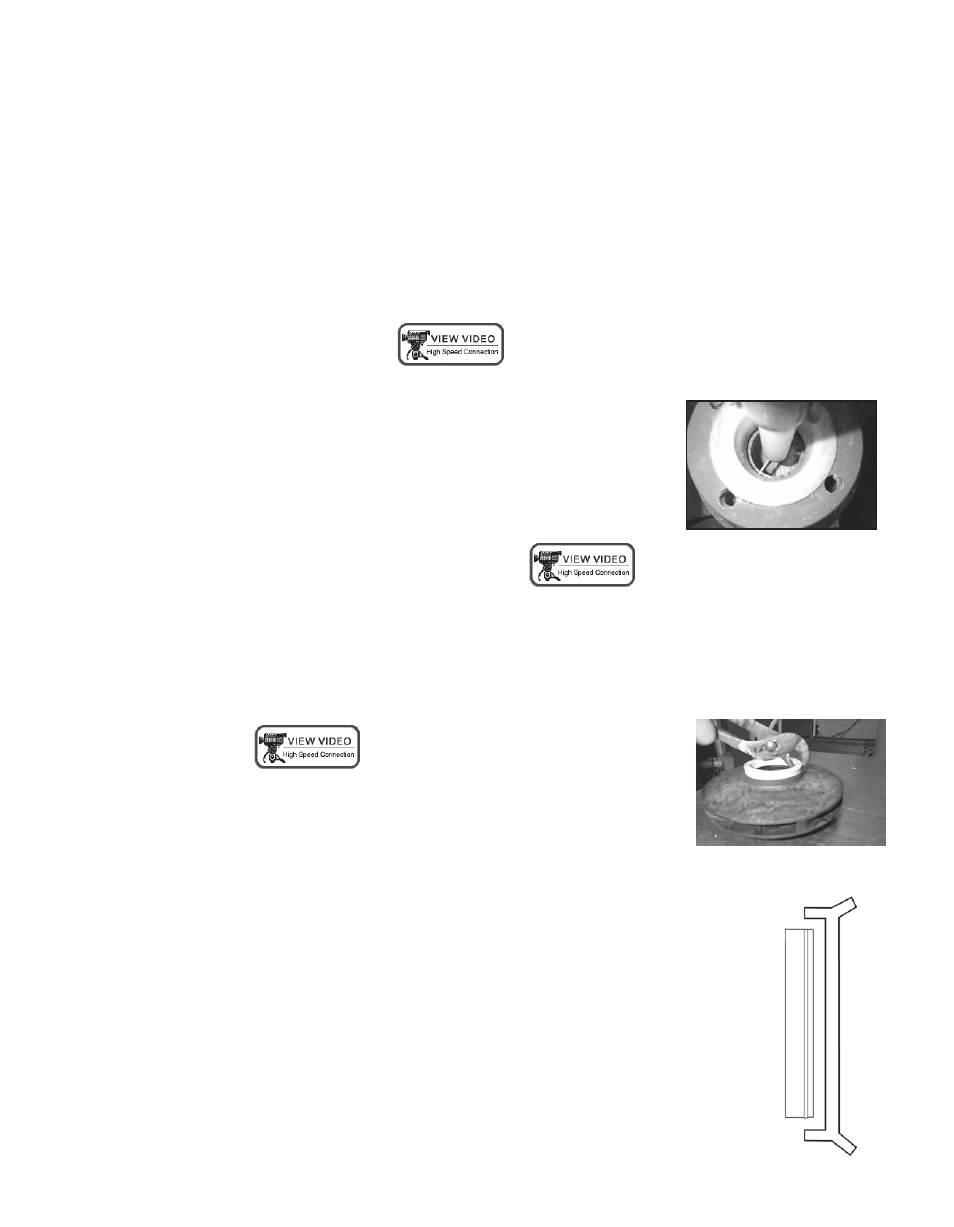
Removal
1. The impeller thrust ring (item 3A) is removed by grabbing the top of the ring with pliers and
pulling with a twisting motion. Be careful not to damage the bore or face of the front impeller
shroud.
See figure 20.
Note: A new impeller thrust ring will be required after removal.
Replacement
1. Place the impeller and impeller drive assembly (items 3,3A, 4,4A, 4B, 4C) on a table with the
suction side facing up.
2. Position the replacement impeller thrust ring in the bore of the front shroud with the snap fit
ridge towards the bottom of the bore. See figure 21. Align the anti-rotation flat on the impeller
thrust ring with the flat in the impeller shroud.
3. Place the impeller and impeller drive assembly in an arbor press. Using a soft faced arbor,
gently press the impeller thrust ring into place.
figure 20
figure 21