Finish Thompson UC User Manual
Page 14
14
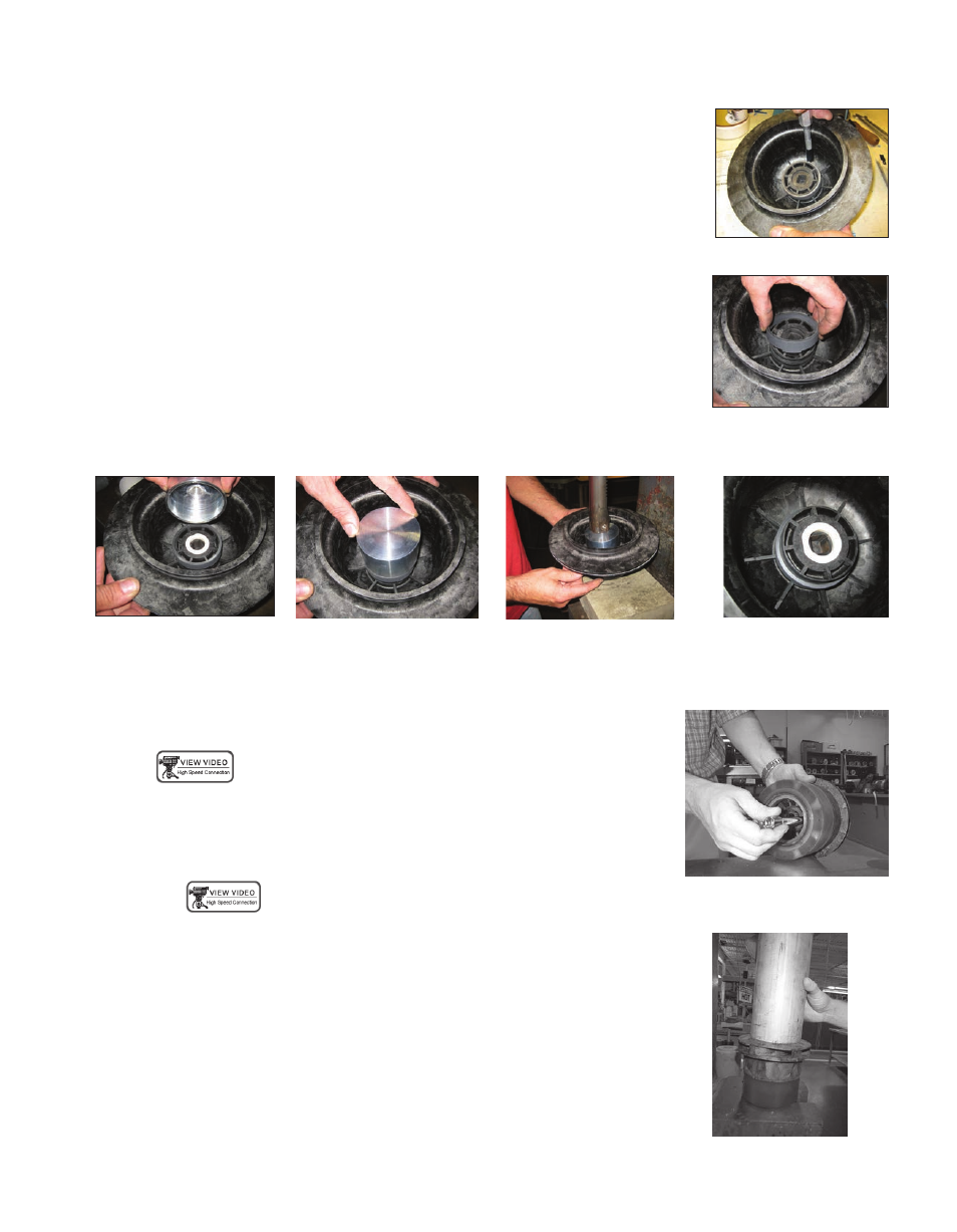
Rear Sealing Ring
The rear sealing ring (item 4C) is located in the rear bore of the barrier assembly (item 6).
Removal
1. Place barrier (item 6) on a table with open side facing up.
2. Remove rear sealing ring by cutting it with a #18 straight edge X-Acto knife or similar blade &
gently cut through the ring. Once cut, simply spread open and remove the ring from the barrier
inner shaft boss. See figure 22.
Replacement
1. Place barrier (item 6) in an arbor press with the open side facing up.
2. Place the rear sealing ring on the inner shaft boss of the barrier assembly, align the two tabs so
they will fit in between the ribs located in the bottom of the barrier. See figure 23.
3. Gently press the ring into place evenly using an arbor press and a 2.68” (68 mm) diameter tool.
Note: this is the minimum inner diameter for the tool to fit over the rear shaft boss. See figures
24, 25, 26.
4. Ring is fully seated when it “snaps” into the machined groove on the boss, roughly 3/8”
(9.5 mm) from the top of the boss. See figure 27.
figure 24
figure 23
figure 22
figure 25
figure 26
figure 27
Impeller Assembly Removal and Replacement
The impeller assembly can be replaced as required to change the impeller diameter or replace
damaged or worn vanes.
Removal
1. Holding the impeller and impeller drive assembly (items 3,3A, 4,4A, 4B, 4C) by hand, place
a 3/8-inch diameter rod (or a 3/8” ratchet extension) through the perforations in the bore of
the impeller drive assembly (item 4).
2. While holding the impeller drive assembly tap on the rod with a hammer in several locations
until the impeller assembly separates from the impeller drive assembly. See figure 28.
Replacement
1. Place the impeller drive assembly in an arbor press with the rear sealing ring facing down.
2. Align the kidney-shaped drive pins on the impeller assembly with the kidney-shaped slots in
the impeller drive assembly and press partially in by hand.
3. Complete installation by pressing the impeller assembly into the impeller drive assembly
with an appropriate size arbor (be sure the arbor does not touch the impeller thrust ring,
item 3A, use an arbor with a larger diameter than the eye of the impeller) until the back side
of impeller rear shroud is flush with front face of impeller drive assembly. See figure 29.
figure 28
figure 29