Farm Star MDM70-72C 6 User Manual
Page 27
17
26
T R A C T O R R E Q U I R E M E N T S
A N D P R E PA R AT I O N
The models MDM 70-60, MDM 70-60C, MDM 70-72
and MDM 70-72C Medium Duty Mowers require a
Category I 3-pt. hitch tractor of at least 25 horsepower for
5’ mowers and 35 horsepower for 6’ mowers and
equipped with a 540 rpm PTO (power takeoff) in good
working condition.
It is recommended that only tractors with wide front
axles be used with this cutter. Tricycle front wheel
arrangements are inherently unstable and tractor
roll-over accidents are more likely to occur.
The tractor also needs lift arm stabilizer bars or sway
blocks to control side movement of the cutter.
Check the tractor’s 3-pt. hydraulic lift system. Refer to
your tractor operator’s manual or dealer for any adjust-
ments necessary to put the hydraulic system in good
working order. (I&T shop manuals will list most specifi-
cations and adjustment instructions - available from most
farm equipment dealers.)
Be sure tires and rims are in good condition. Inflate
tires to the proper recommended air pressure.
All tractors that are not equipped with a “live” power
takeoff (PTO) need to be equipped with an over-running
PTO clutch.
Check the tractor master shield over the PTO stub
shaft. Make sure it is in good condition and fastened
securely to the tractor. Purchase a new shield if old
shield is damaged or missing. (You may have to use a
tractor salvage yard for replacement parts on older
tractors.)
It is recommended that a ROPS (Roll-Over Protection
Structure) and a seat belt be installed on all tractors.
Contact your local dealer for a ROPS for your tractor.
C A U T I O N !
Be sure your tractor is in good condition. Read all
the safety precautions and make sure all tractor
operators are familiar with the safety rules of
operation.
Figure 1. Tractor Stability
W A R N I N G !
When using the unit, a minimum 20% of tractor and
equipment weight must be on tractor front wheels.
Without this weight, tractor could tip up, causing
possible loss of control and possible personal injury
or death. The weight may be attained with a front
end loader, front wheel weights, ballast in tires or
front tractor weights. When attaining a minimum
20% of tractor and equipment weight on the front
wheels, you must not exceed the ROPS weight
certification. Weigh the tractor and equipment. DO
NOT GUESS OR ESTIMATE!
W A R N I N G !
A heavy load can cause instability in driving a
tractor. Make sure the front of the tractor is properly
counterbalanced with weights. Always drive slowly -
especially around turns. An unstable tractor could
steer badly and possibly tip over, causing injury or
death.
D A N G E R !
FOR AGRICULTURAL USE ONLY!
When this equipment is operated in populated
areas or other areas where thrown objects could
injure persons or property, full chain or rubber
shielding (which is designed to reduce the possibili-
ty of thrown objects) must be installed. If this
machine is not equipped with full chain or rubber
shielding, operation must be stopped when anyone
comes within several hundred feet.
I N S T R U C T I O N S
The operator is responsible for the safe operation of this
mower. The operator must be properly trained. Operators
should be familiar with the mower and tractor and all
safety practices before starting operation. Read the
safety rules and safety signs on pages 4-16.
This medium duty mower is designed for grass and
weed mowing, stalk shredding, and cutting brush up to 2
inch diameter.
Recommended mowing speed for most conditions is
from two to five mph.
O W N E R S E RVICE
(continued)
R E PAIR OF OPTIONAL
C H A I N S H I E L D I N G
Inspect chain shielding each day of operation and
replace any broken or missing chains as required.
S L I P C L U T C H A D J U S T M E N T
The slip clutch is designed to slip, protecting the gear-
box and driveline, should the cutter strike an obstruction.
A new slip clutch, or one that has been in storage over
the winter, may seize. Before operating, make sure it will
slip by performing this operation:
Make sure tractor engine is turned off and key is
removed.
Remove driveline from tractor PTO.
The slip clutch is factory preset to the correct torque for
protecting implement and tractor.
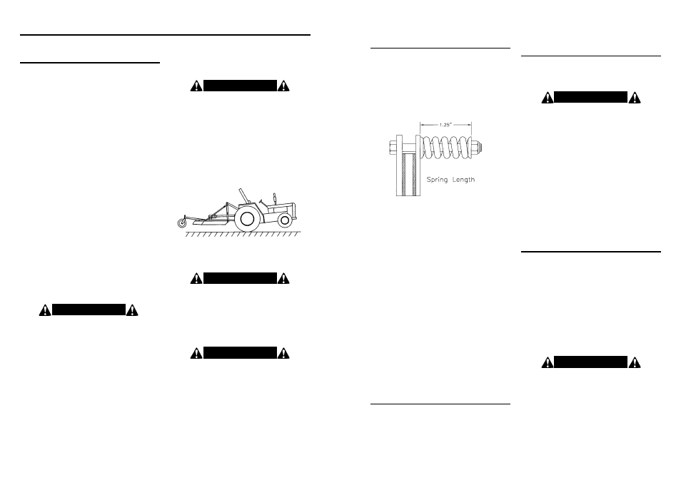
Loosen the eight bolts to remove all tension from
springs (until spring can be turned with fingers).
Hold clutch hub solid and turn shaft to make sure clutch
slips.
If clutch does not slip freely, disassemble and clean the
faces of clutch plate, yoke and plate, and clutch hub.
Reassemble clutch.
Tighten each of the eight bolts evenly until the springs
are compressed to 1.25” as shown in figure 9. If neces-
sary, adjust nut on any spring that is unequal. Adjust all
eight spring retaining nuts 1/3 of a turn (2 flats on a nut)
and check clutch slippage. If further adjustment is nec-
essary, do so in 1/3 increments. Adjust only to provide
sufficient torque to prevent slippage under normal condi-
tions. Occasional slippage is normal for drivetrain pro-
tection. If satisfactory results cannot be obtained, consult
your dealer.
If a clutch continues to slip when the springs are com-
pressed to 1.25”, check friction disc for excessive wear.
Discs are 1/8” when new. Replace discs after 1/16” wear.
Minimum disc thickness is 1/16”.
B L A D E B E A M & G E A R B O X
R E M O VA L
A. Raise mower using tractor 3-point lift. Turn off tractor
engine.
B. BLOCK MOWER SECURELY INTO POSITION.
B L A D E B E A M & G E A R B O X
I N S TA L L AT I O N
A. Raise mower using tractor 3-point lift. Turn off tractor
engine.
B. BLOCK MOWER SECURELY INTO POSITION.
C. Attach gearbox to mower deck using bolts and nuts.
D. Install blade holder onto gearbox securing with
castellated nut and flat washer. Torque nut to 350
ft./lbs. Wear heavy work gloves to protect hands from
sharp edges.
E. Install cotter pin to retain nut. It may be necessary to
slightly loosen nut to install cotter pin.
F. Slide driveline yoke onto gearbox input shaft. Install
retaining clip and shear bolt. (Shearbolt Models)
C. Remove cotter pin and blade holder retaining nut.
Wear heavy work gloves to protect hands from sharp
edges.
D. Grasp blade holder and pull off shaft. If necessary,
align blade bar with access hole in top of deck and
drive off with hammer and pipe. Care should be taken
not to damage threads on blade bolt.
E. Press all three tabs and slide yoke shield back.
F. Remove shear bolt and retaining clip. Slide yoke off
gearbox input shaft.
G. Remove nuts securing gearbox to deck. Remove
gearbox.
G. Lock driveline yoke shield securely into place.
H. Fill gearbox with oil to proper level.
W A R N I N G !
DO NOT GET UNDER MOWER UNLESS IT IS
SECURELY BLOCKED IN POSITION. ACCIDENTAL
FALL COULD CAUSE SERIOUS INJURY OR DEATH.
W A R N I N G !
ON SHEARBOLT MODELS, FAILURE TO INSTALL
RETAINING CLIP WILL ALLOW DRIVELINE TO COME
OFF GEARBOX AND SWING FREELY IF BOLT IS
SHEARED CAUSING POSSIBLE INJURY OR DEATH.
Figure 9.