Farm Star MDM70-72C 6 User Manual
Page 26
25
18
I N S T R U C T I O N S
(continued)
A T TA C H M E N T
The mower is shipped partially assembled. Assembly
will be easier if components are aligned and loosely
assembled before tightening hardware. Recommended
torque values for hardware are located on page 26.
Select a suitable working area. Refer to illustrations,
accompanying text, parts lists and exploded view
drawings.
Complete check lists on page 20 when assembly is
complete.
Position mower flat and cut the nylon straps that are
holding all loose parts to the mower.
Rotate the “A” frame hitch forward and connect lift arms
and toplink.
Attach the two linkage lift straps to the mower deck
(behind the gearbox) and to the end of the slack link on
the “A” frame. These bolted connections are moveable
joints – so tighten nylock nuts only until excess loose-
ness is gone.
Most swinging drawbars will have to be moved to a
forward position or removed. Check the tractor swing-
ing drawbar for interference with the front of the mower
and PTO driveline before attempting to lift the mower
with the 3-pt. hitch.
Tractor lift arm stabilizer bars or sway blocks must be
used to control side movement of the cutter. DO NOT
CONNECT THE PTO DRIVELINE AT THIS TIME.
Check your lift arm hydraulic controls. Be sure the
hydraulic 3-pt. hitch control is in the float position and the
draft control is turned off.
Adjust lower lift arm(s) to level mower right to left. Refer
to tractor operator’s manual for instructions.
Cutting height is controlled with tractor 3-point arms,
and rear tailwheel adjustment.
PTO DRIVELINE INSTA L L AT I O N
On new mowers, check PTO driveline for correct length
for use with your tractor. (Read page 19.)
SHEARBOLT MODELS
Spray WD-40 into the yoke and wipe. This should
remove some of the paint and make it easier to slide the
yoke onto the input shaft of the gearbox.
Remove shearbolt and retaining ring (4) from gearbox
input shaft (3).
Grease the input shaft of the gearbox before installing
the PTO shaft. This reduces the chance of the PTO shaft
yoke from galling to the input shaft if the shear pin should
break.
Remove rear drive shield (1) from driveline. To remove,
turn each plastic clip
1
/
4
turn and then lift out. Then slide
rear shield so entire joint assembly is exposed. (Refer to
figure 2.)
To prevent seal damage, carefully push driveline onto
gearbox input shaft until it contacts gearbox housing.
Install retaining ring (4) and then pull driveline ahead.
1. Drive shield
3. Input driveline shaft half
4. Retaining ring
5. Nut
6. Shearbolt grade 5 (
1
/
2
– 13 NC x 3” long)
7. Gearbox input shaft
Figure 2. Shear Bolt Driveline Installation
NOTE: A grade 5 bolt must be used for the shear bolt
to provide gearbox protection.
Align the holes in the driveline yoke and gearbox input
shaft and install and tighten shear bolt (6) and nut (5).
Install rear drive shield to driveline.
Lubricate rear driveline half and install front driveline
half.
SAFETY . . .
YOU CAN LIVE WITH IT!
NOTE: Front chain guards are required on this mower
when it is to be operated along roadsides or where
people, livestock, or property is present.
Even when chain guarding is used, it is recommended
to stop operation if people are present within 100 feet of
the mower.
ALWAYS USE CAUTION!
O W N E R S E RVICE
(continued)
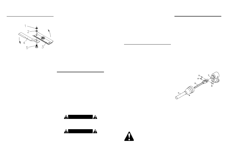
B L A D E S E RV I C I N G
BLADE REMOVAL
(Figure 8)
1. Jam nut
2. Lockwasher
3. Blade beam
4. Blade
5. Blade bolt
Figure 8. Blade Installation
S H E A R B O LT R E P L A C E M E N T
Remove driveline shield bell. (Refer to page 19 for
instructions.)
Make sure the input shaft of the gearbox is greased.
This reduces the chance of the PTO shaft yoke from
galling to the input gearbox shaft if the shear bolt should
break.
Rotate driveline to align holes in yoke and shaft. Install
shear bolt and secure with locknut. Replace driveline
shield bell.
Disconnect driveline from tractor PTO.
It is necessary to gain access to bottom side of mower
for blade removal. Raise mower and block securely.
Align crossbar (3) with blade access hole in the mower
deck. Remove nut (1) and lockwasher (2) then carefully
drive bolt (5) out of crossbar.
Insert blade bolt (5) through blade, align key on blade
bolt with keyway in blade beam and push blade bolt
through blade beam. Insert lockwasher (2) and nut (1)
through blade access hole in the mower deck, install on
bolt (5) and tighten to 350 lbs.-ft.
Repeat for opposite blade.
Sharpen both blades at the same time to maintain bal-
ance. Follow original sharpening pattern. Do not sharpen
blade to a razor edge, but leave at least a
1
/
16
” blunt edge.
Do not sharpen back side of blade.
Rotate blade beam (3) and repeat for opposite blade.
Always replace or sharpen both blades at the same
time.
Inspect blade bolt (5) for nicks or gouges; replace if any
are found. Insert bolt through blade. Blade should swivel
on bolt. Determine cause if it does not and correct.
Align blade beam (3) with blade access hole in the
mower frame. Apply a liberal coating of Never Seez
®
or
equivalent to blade bolt and blade beam hole. Make sure
blade is offset away from mower.
Never Seez is a registered trademark of the
Never Seez Corporation.
W A R N I N G !
FAILURE TO USE CORRECT SIZE SHEAR BOLT
MAY CAUSE PERSONAL INJURY OR DEATH.
W A R N I N G !
FAILURE TO INSTALL RETAINING CLIP WILL
ALLOW DRIVELINE TO SWING FREELY IF BOLT IS
SHEARED CAUSING POSSIBLE INJURY OR DEATH.
IMPORTANT
If blade bolt (5) is seized in blade beam and extreme
force is required to remove it, support blade beam
from below to prevent gearbox damage.
IMPORTANT
When sharpening blades, grind each blade the
same amount to maintain balance. Replace blades in
pairs. Unbalanced blades will cause excessive vibra-
tion which can damage gearbox bearings. Vibration
may also cause structural cracks to mower.
IMPORTANT
Always use approved
1
/
2
” NC x 3” grade 5 shear bolt
as a replacement part. Using a hardened bolt or
shear pin may result in damage to driveline or
gearbox.
IMPORTANT
Blade beam rotation is counter-clockwise when
looking down on mower. Be sure to install blade cut-
ting edge to lead in counter-clockwise rotation.
BLADE SHARPENING