Load cell testing, Load cell replacement – Fairbanks Aegis Transport Scale User Manual
Page 21
Section 3: Service & Maintenance
04/10
21 51191 Rev. 2
3.2.3. Load Cell Testing
When corners do not match the correct tolerances, disconnect/cut each Load Cell
Cable at the Wheel Base Access Area, then test each Load Cell for the settings on
the following chart.
TEST
READING
REMARKS
Green to Black (Input)
1106 Ohms (+5 / -2 Ohms)
Input Resistance
Red to White (Output)
1000 Ohms (+5 / -2 Ohms)
Output / Bridge Resistance
Yellow (Shield) to Load Cell Case
More than 1,000 megohms
Insulation Resistance
Input and Output Leads to Shield
Input and Output Leads to Case
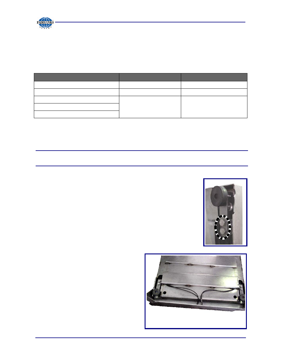
3.2.4. Load Cell Replacement
NOTE:
A Torque Wrench of up to 90 ft/lbs must be used when replacing the Load
Cells.
1. Remove the two bolts securing each Load Cell to its
mounting block.
2. Pull away the Load Cell from the Platform.
3. Follow the Interface Cable down through Pillar Access Hole
to the Side Rails to either the Junction Box (for Stainless
Steel Models), or the Summing Area (for Mild Steel
Models).
─ Pull the cable back and forth to be certain it is the correct
one.
─ Make a note of the cable routing
design and the wiring
connections.
Load Cells are in the
nearest position to
the Access Hole.