1 main power board, Green class net meter – E-Mon E50-6003200J*-N-KIT User Manual
Page 6
GREEN CLASS NET METER
62-0416-01
6
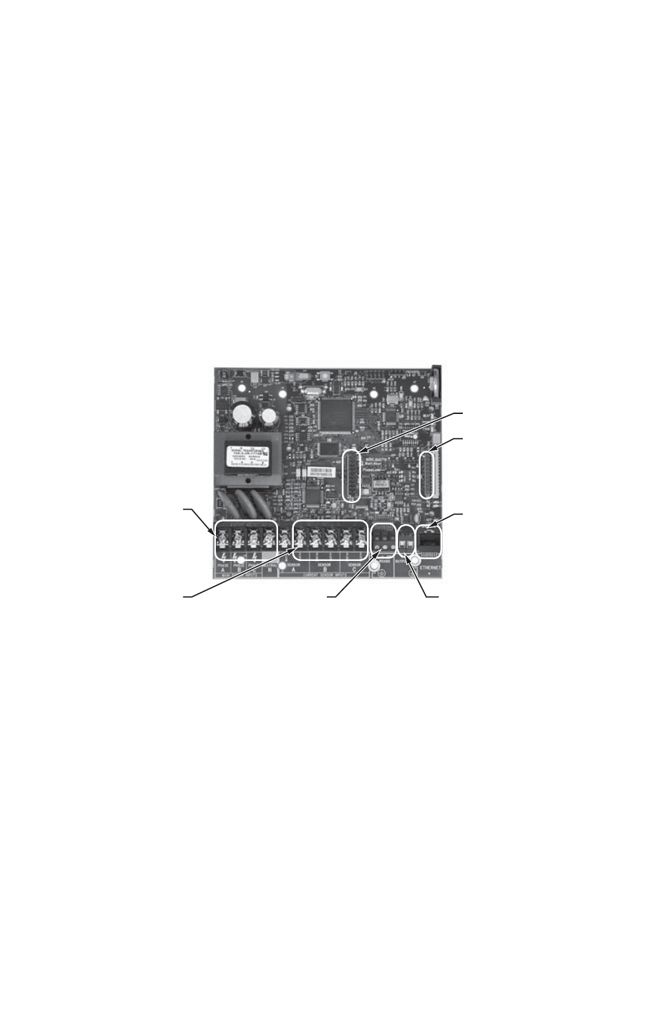
2.1 Main Power Board
Connections to this board include the MAIN Power Input and current sensors. The
MAIN Power Input terminals are positions one through four on the four position screw
terminal block, TB1. These terminals are covered with a protective shield for safety
purposes. The current sensor assemblies interface to the TB2, TB3 and TB4. Each
terminal block corresponds to an input voltage phase; care must be exercised to
ensure that each current sensor is connected to the correct terminal block. One three
terminal screw connector(TB42) is provided for RS-485 communications. One RJ-45
jack (J8) is provided for 10/100-base T Ethernet. One two terminal screw connector
provides phase loss alarming.
There are also two headers present for adding option cards. Header J3 is 20 positions
for use with an I/O board with up to two relays, two pulse inputs and two pulse out puts.
Header J4 is a 10 positions for use with modem and LonWorks TP/FT-10.
Fig. 2. Main Power Board Connections.
M33271
TB1
POSITIONS
POSITIONS
6-10
PHASE LOSS
TB42
J3
J4
J8
- E50-6001600J*-N-KIT E50-600800-J*-N-KIT E50-600400-J*-N-KIT E50-600200-J*-N-KIT E50-600100-J*-N-KIT E50-4803200J*-N-KIT E50-4801600J*-N-KIT E50-480800-J*-N-KIT E50-480400-J*-N-KIT E50-480200-J*-N-KIT E50-480100-J*-N-KIT E50-4003200J*-N-KIT E50-4001600J*-N-KIT E50-400800-J*-N-KIT E50-400400-J*-N-KIT E50-400200-J*-N-KIT E50-400100-J*-N-KIT E50-2083200J*-N-KIT E50-2081600J*-N-KIT E50-208800-J*-N-KIT E50-208400-J*-N-KIT E50-208200-J*-N-KIT E50-208100-J*-N-KIT