Teledyne 4040 - Methane / Nonmethane analyzer User Manual
Page 39
Installation
Teledyne
Analytical
Instruments
39
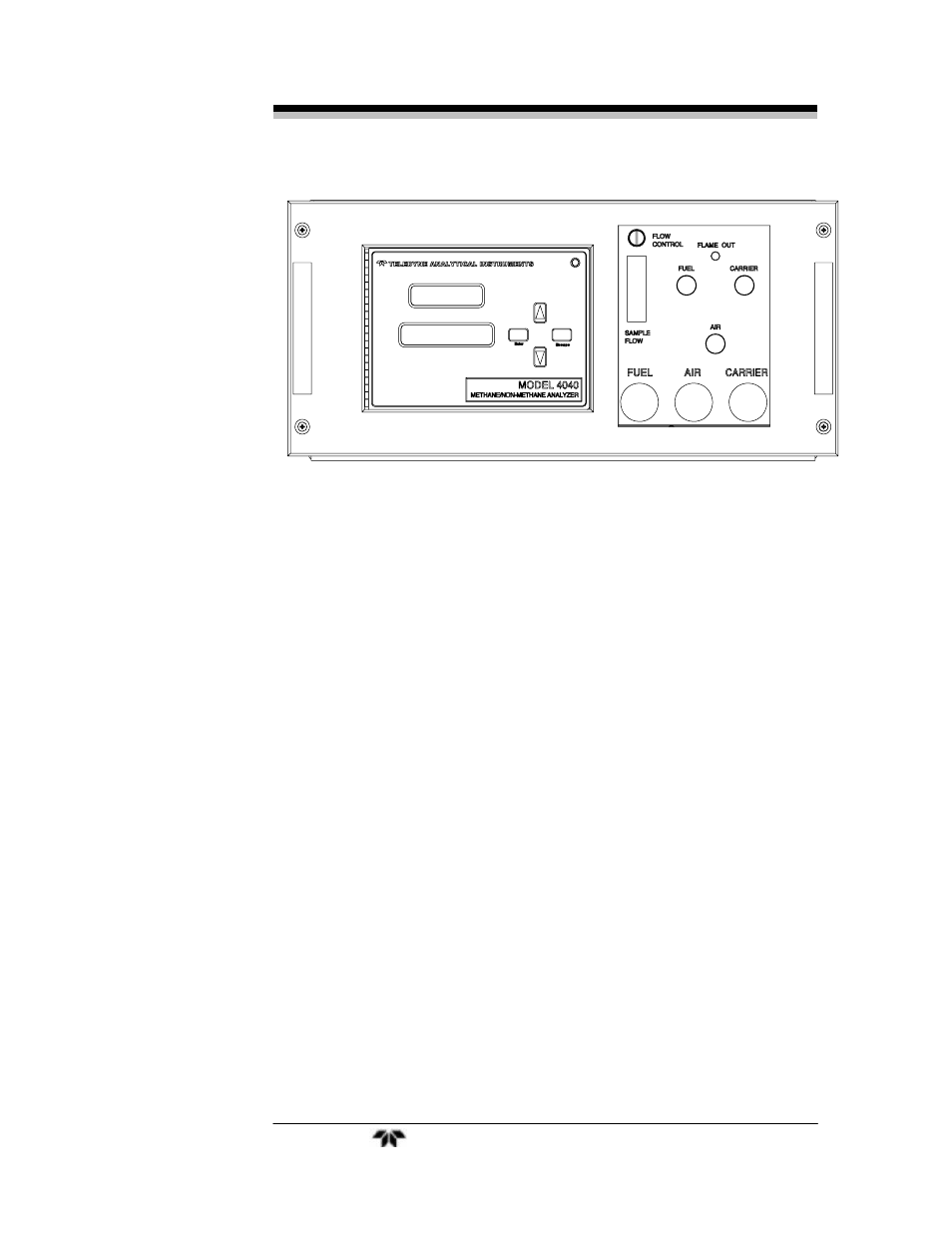
Figure 3-3: Front Panel View of Regulator and Gages
3.6 Flame Ignition
Observe that after warm up count down timer reaches zero (timer to
preheat the sensor), the amber heater lamp is blinking (indicating that
the temperature controller is maintaining the temperature setpoint) and
the red flame failure lamp is on. See Figure 4-1.
The Series 4040 will automatically attempt a flame ignition
sequence following the warm up period, which has been preset at the
factory. If the ignition process fails, the instrument will attempt to ignite
the flame 4 more times. If it continues to fail after the fifth attempt, a
flame failure message will appear on the display. If this occurs refer to
Section 5.
3.6.1 Verification of the Flame Guard Circuit
The operation of the flame guard circuit has been checked at the
factory, but should be re-verified during start-up. Use the following
procedure after ignition of the flame has been achieved:
1. Turn off the fuel at the supply cylinder.
2. Observe the fuel pressure gauge on the analyzer control panel. The
gauge indication will decay as the fuel in the line is exhausted.
When the gauge reading reaches the vicinity zero, the flame will
be extinguish as the fuel solenoid shuts off the fuel supply. The
analyzer will automatically try to re-ignite. After 5 attempts, it will